SsangYong Korando II (1996-2006 year). Manual — part 146
OM600 ENGINE MECHANICAL 1B3 -- 33
DAEWOO MY_2000
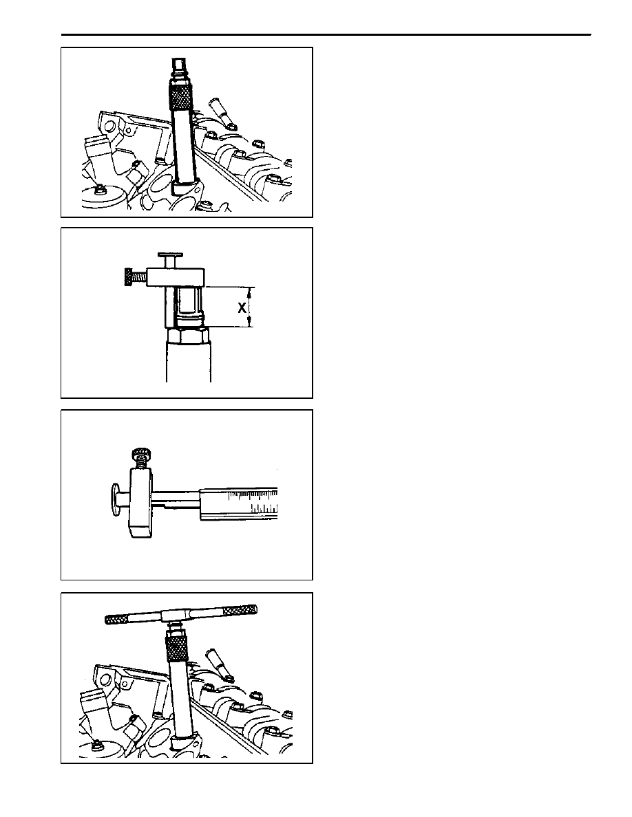
1. Remove the injection nozzle.
2. Remove the prechamber.
3. Cover the prechamber bore to avoid any chips drop-
ping into the combustion chamber.
4. Remove the protective sleeve from the countersink
and rotate the countersink into the prechamber bore
to be machined as far as the stop.
Counter Sink 601 589 00 66 00
5. Maintain size ’X’ from the top edge of mandrel to the
top edge of the sleeve with the gauge.
Height Gauge 667 589 00 23 00
6. Measure the ’X’ by using a vernier caliper.
7. Mount the turning tool onto the countersink tool and
rotate to the right approx. 5 revolutions by applying
slight pressure.
1B3 -- 34 OM600 ENGINE MECHANICAL
DAEWOO MY_2000
8. Remeasure size ’X’ and compare it with the first
measurement and determine the thickness of
spacer ring.
Ex
Size before machining
25.7 mm
Size after machining
25.5 mm
The spacer ring should be selected so that it is at
least 0.1mm and not more than 0.3mm thicker than
the measured on the sealing surface. In this exam-
ple, the necessary thickness of spacer ring should
be within 0.3 ~ 0.5mm and the thickness of spacer
ring to be installed is 0.3mm.
9. Remove the countersink tool and clean the chips.
Notice
If the sealing surface is not completely flat, rema-
chine the sealing surface.
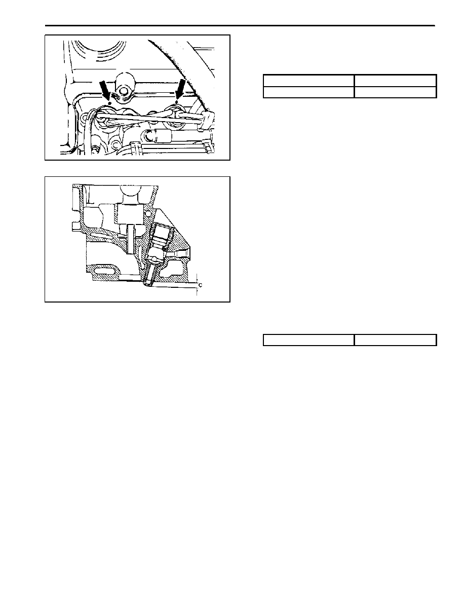
10. Remove rag from the prechamber bore and crank
the engine with starter motor to threw out any chips
which may have got into the combustion chamber.
11. Insert the proper spacer ring into the prechamber
sealing surface.
12. Punch a mark on the cylinder head above the pre-
chamber sealing surface which has been machined.
13. Install the prechambers.
Notice
If the cylinder head is removed, the projection ’C’ is
measured in place of size ’X’ and the appropriate
size of spacer ring selected.
Normal Projection (c)
7.6 -- 8.1mm
OM600 ENGINE MECHANICAL 1B3 -- 35
DAEWOO MY_2000
TDC (TDC SENSOR BRACKET) SETTING
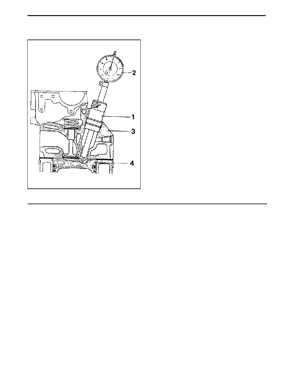
Preceding Work : Removal of No.1 cylinder prechamber
1 Measuring Device
2 Dial Gauge
3 Cylinder Head
4 Piston
Set at TDC
. . . . . . . . . . . . . . . . . . . . . . . .
Tools Service
001 589 32 21 00 Dial Gauge
601 589 07 21 00 Depth Gauge
667 589 01 21 00 Fixing Device
Notice
D
The TDC sensor bracket must be adjusted in case
of followings.
D
When replacing the TDC sensor bracket.
D
When replacing the crankshaft, the hub or the
vibration damper.
D
lWhen replacing or installing the timing case cover.
D
After engine overhauling.
*
If the cylinder head is removed, the measuring pin of
the dial gauge can be positioned on the piston
crown.
This is done by placing the magnetic dial holder on
the mating surface of the crankcase.
1B3 -- 36 OM600 ENGINE MECHANICAL
DAEWOO MY_2000
Setting (with cylinder head installed)
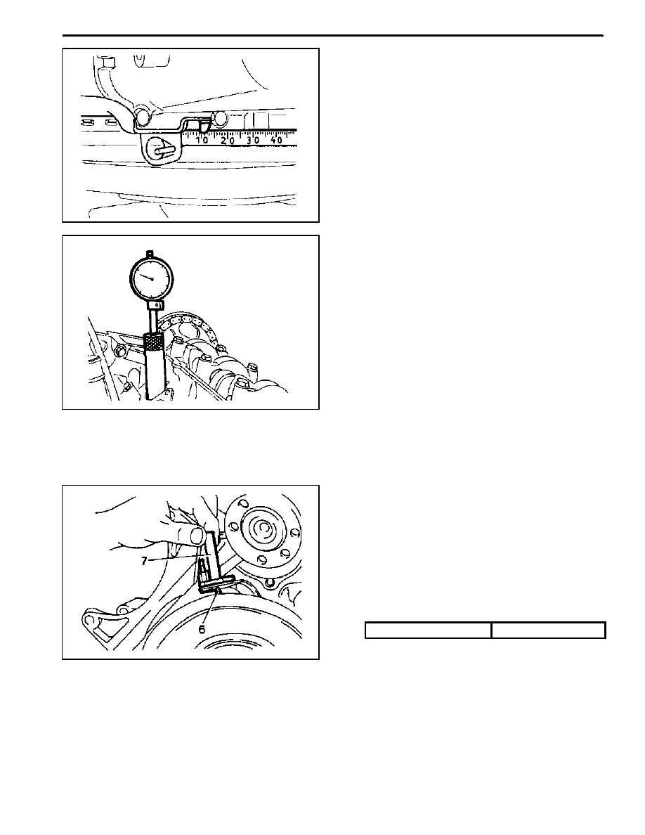
1. Remove the prechamber of No. 1 cylinder.
2. Position the piston of No.1 cylinder at BTDC 10.
3. Install the measuring device into the prechamber
bore and position the dial gauge with a preload of
5mm.
Dial Gauge 001 589 53 21 00
Depth Gauge 601 589 07 21 00
4. Slowly rotate the crankshaft in the direction of en-
gine rotation until the large pointer on the dial gauge
stops (TDC position).
Notice
The position of TDC is when the large pointer on the
dial gauge is stopped before moving back.
5. Remove the reinstall the measuring device and
position the dial gauge scale at ’0’.
6. Slowly rotate the crankshaft in the direction of en-
gine rotation until the dial gauge has moved back
(counterclockwise) by 3.65mm.
7. Insert fixing device into the sensor bracket.
Notice
The pin on the vibration damper must engage into
the slot of the fixing device.
Fixing Device 667 589 01 21 00
8. If the pin does not engage, adjust the setting of the
sensor bracket by removing and tightening of the
sensor bracket bolts.
Tightening Torque
10 N∙m (89 lb-in)
Notice
The timing mark on the damper must be positioned
at ATDC 20.
Нет комментариевНе стесняйтесь поделиться с нами вашим ценным мнением.
Текст