SsangYong Korando II (1996-2006 year). Manual — part 317
AUTOMATIC TRANSMISSION 5A-171
SSANGYONG MY2002
ASSEMBLY PROCEDURE
Transmission
Tools Required
0555-336256 Transmission Bench Cradle
0555-336258 Cross Shaft Pin Remover/Installer
(Detent Lever)
0555-336262 Cross Shaft Seal Installer
0555-336263 Cross Shaft bullet
0555-336265 Cross Shaft Pin Remover/Installer
(Inhibitor Switch)
Notice:
•
The transmission is assembled in modular fashion
and details of assembly for each module are given
under the appropriate subject.
•
Technicians overhauling these transmissions will
also require a selection of good quality Torx bit
sockets, in particular numbers 30, 40 and 50, and
an 8 mm, 10 mm and 12 mm double hex socket.
•
Ensure that the B1R circlip is fitted to the case. (If
this is not fitted, the valve will peen its way into
and through the separator plate)
•
Ensure that the ’E’clip is fitted to the cross shaft.
•
Ensure that all aspects of the parking mechanism
are working.
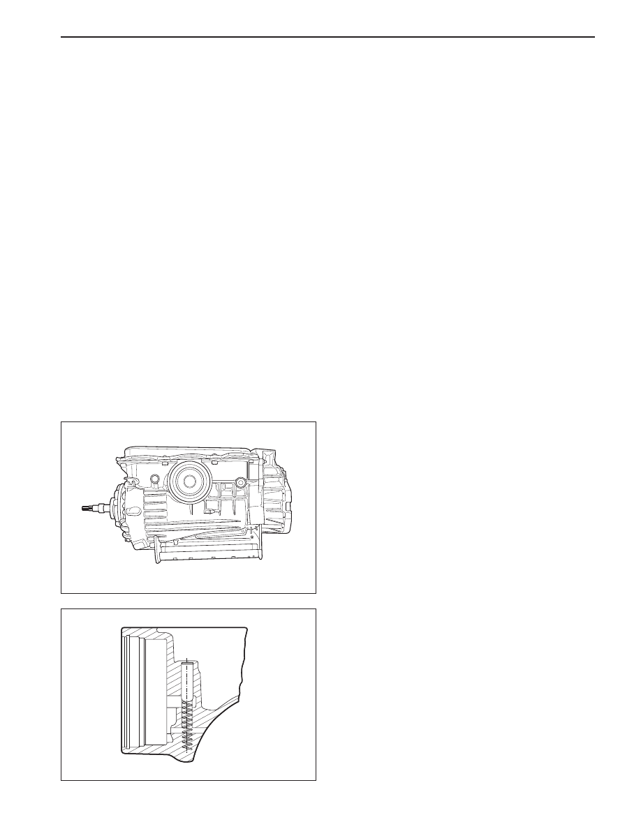
3. Assemble the B1R valve and spring, and secure
with the circlip. Ensure that the circlip is completely
seated in its groove.
1. Turn the transmission case upside down on the
bench and mount it to the transmission bench cradle
0555-336256.
2. Install all fittings, plugs and the breather, applying
a sealant where applicable, Tighten the fittings to
specifications. Ensurethatthebreatheris clear,
andcheckthat the lube fitting in the rear of the case
is fittedand clear of obstruction.
KAA5A500
KAA5A880
5A-172 AUTOMATIC TRANSMISSION
SSANGYONG MY2002
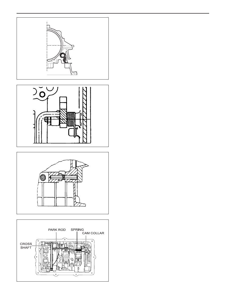
4. Install the rear servo lever and pivot pin.
Notice: The lever must pivot freely on its pin.
5. Assemble the park rod lever, complete with the
return spring and pivot pin, applying a small
amount of sealant to the outer end of the pivot
pin.
Notice: Care must be taken when applying sealant
to ensure that it is not applied between the pin and
the lever.
6. Secure the pivot pin with the circlip.
Notice: The lever must pivot freely on its pin and
the spring must return the park rod lever to its correct
location.
7. Install the parking pawl pivot pin and spring.
Notice: The pawl must pivot freely on its pin.
8. Connect the park rod to the manual valve detent
lever. Ensure the spring and cam collar is firmly
installed on the rod.
9. Check that the cam collar slides freely on the rod.
10. Insert the cross shaft into the case, from the side
opposite to the inhibitor switch, then install the
antirattle spring on the shaft.
KAA5A890
KAA5A640
KAA5A900
KAA5A910
AUTOMATIC TRANSMISSION 5A-173
SSANGYONG MY2002
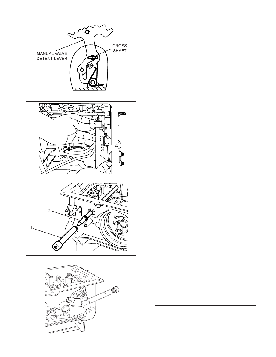
11. Poition the manual valve detent lever, aligning it
with the cross-shaft bore in the case.
12. Push the shaft through the detent lever until it
starts in the detent lever side of the case.
16. Install the new cross shaft seals using cross shaft
seal installer 0555-336262 (1) and cross shaft
bullet 0555-336263 (2).
17. Install the inhibitor switch on the case. Torque the
bolts as per specifications. Press the pin into the
shaft until the tool bottoms using cross shaft pin
installer/ remover (inhibitor switch) 0555-336265.
Installation Notice
18. Thoroughly check the terminal wiring loom for
condition and continuity.
13. Install the detent lever drive pin in the shaft using
cross shaft pin remover/installer (detent lever)
0555-336258 with the adaptor over the pin.
14. Press the pin into the shaft until the tool bottoms.
15. Remove the tool and fit the spring retaining circlip
to the shaft.
KAA5A920
KAA5A600
KAA5A930
KAA5A580
Tightening Torque
4 - 6 N•m
(35 - 53 lb-in)
5A-174 AUTOMATIC TRANSMISSION
SSANGYONG MY2002
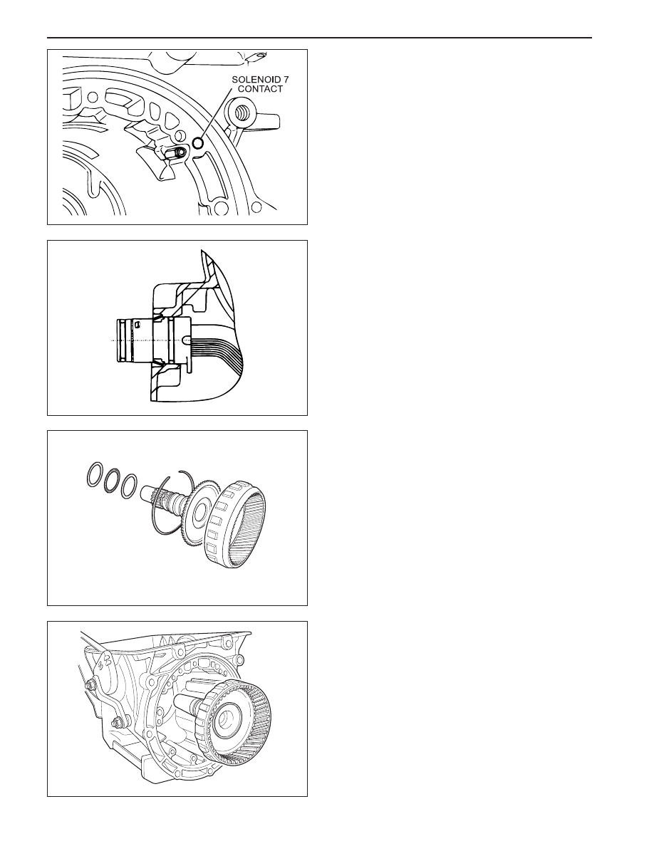
19. Position the wiring loom and locate the solenoid 7
contact and terminal in the pump mounting flange
at the front of the case. The solenoid 7 wire is
routed under the park rod and cross shaft in the
case.
20. Install the 10 pin connector in the case engaging
the tangs on the connector in the notches in case.
Output Shaft and Gear Assembly
1. Check that the output shaft bush is not worn or
damaged. Replace if necessary.
2. Check for damage to parking pawl teeth on the
ring gear. Replace if necessary.
3. Check that the sealing ring grooves have not been
damaged.
4. Lubricate the sealing rings with automatic
transmission fluid.
5. Assemble the sealing rings to the output shaft
with the scarf cut uppermost.
6. If previously dismantled, assemble the ring gear
to the output shaft and secure with circlip. Ensure
that the circlip is firmly seated in its groove.
7. Install the No. 10 needle bearing assembly onto
the output shaft using petroleum jelly.
8. Carefully install the output shaft assembly in the
case to prevent damage to the sealing rings.
KAA5A940
KAA5A610
KAA5A970
KAA5A980
Нет комментариевНе стесняйтесь поделиться с нами вашим ценным мнением.
Текст