SsangYong Korando II (1996-2006 year). Manual — part 456
DOORS 9P-5
SSANGYONG MY2002
DOOR LOCK STRIKER
ADJUSTMENT
Installation Notice:
The door lock striker is an important attaching part
that can affect the performance of vital components
and systems and can cause major repair expenses. If
replacement becomes necessary, the door lock striker
must be replaced by one with the same part number
or with an equivalent part. Do not use a replacement
part of lesser quality or of a substitute design. The
s p e c i f i e d t o r q u e v a l u e s m u s t b e u s e d d u r i n g
reassembly in order to ensure the proper retention of
the part.
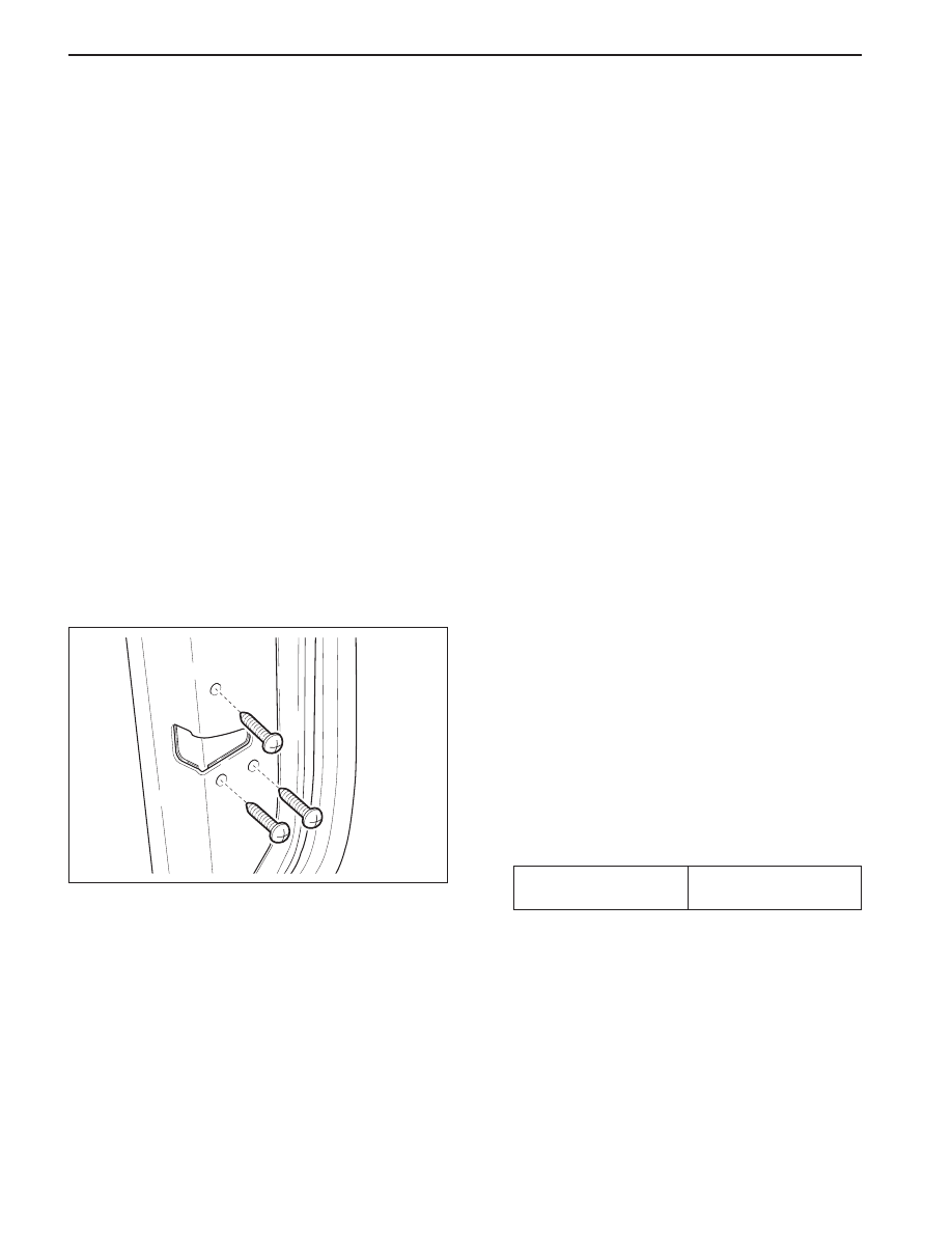
The door lock striker consists of a striker with two screws
that are threaded into a tapped, floating cage plate
located in the appropriate body pillar. This floating
cage plate allows the striker to be easily adjusted in
or out and up or down. The door is secured in the closed
position when the door lock fork snaps over and
engages the striker.
Fore/Aft Adjustment
1. The door must be properly aligned.
2. Close the door until the lock fork contacts the
striker.
3. Stand next to the door opening and move the door
slowly in and out, just touching the striker each
time.
4. The alignment of the lock fork and the striker can
b e e a s i l y s e e n . T h e l o c k f o r k s h o u l d b e
perpendicular to and fall near the middle of the
striker between the B-pillar and the end of the
striker.
5. If a fore or aft adjustment is required, use the
following steps:
5.1 Remove the striker screws.
5.2 Remove the spacer in order to move the striker
toward the front of the vehicle.
5.3 Add a 2 mm (0.8 inch) spacer in order to move
the striker toward the front of the vehicle.
5.4 Install the striker screws.
6. Perform the up/down or the in/out adjustment.
Refer to “up/down or in/out Adjustment” in this
section.
SSANGYONG MY2002
9P-6 DOORS
KAA9P050
FRONT DOOR LOCK
Removal and Installation Procedure
1. Disconnect the negative battery cable.
2. Remove the inside door handle. Refer to “Inside
door Handle” in this section.
3. Disconnect the inside door handle and the lock
rods.
4. Remove the screws and the guide rail.
5. Remove the screws and the front door lock.
Installation Notice
•
Dissimilar metals in direct contact with each
other may corrode rapidly. Make sure to use
the correct fasteners to prevent premature
corrosion.
6. Installation should follow the removal procedure
in the reverse order.
Up/Down or In/Out Adjustment
An adjustment of the striker in the up/down or in/out
directions may be necessary for a number of reasons:
•
Vehicle frame damage as the result of a collision.
•
Installation of new door weather stripping.
•
Customer complaints of excessive wind noise.
•
Difficulty in opening or closing the door.
In order to adjust the door striker in an up/down or in/
out direction, perform the following procedure:
1. The door must be properly aligned.
2. Loosen the striker screws.
3. The floating cage plate can be moved slightly
using the ends of the striker screws. Move the
floating cage plate to the desired position.
Notice: It is important to use a flat-end rotary file in
order not to damage the tapped floating cage plate.
The striker screws and the tapped floating cage plate
are important attaching parts that could affect the
performance of vital components and systems.
4. If proper adjustment requires that the floating cage
plate be moved more than is possible, use an
electric hand drill and a 3/8-inch rotary file with a
flat head in order to enlarge the body opening in
the direction required.
5. Tighten the striker screws to the correct position.
Tightening Torque
6.86 - 9.8 N•m
(5.06 - 7.23 lb-ft)

DOORS 9P-7
SSANGYONG MY2002
KAA9P060
INSIDE DOOR HANDLE
Removal and Installation Procedure
1. Remove the door trim panel. Refer to Section 9G,
Door Trim Panel.
2. Remove the inside door handle with the screws.
3. Disconnect the inside door handle and the lock
rods.
4. Installation should follow the removal procedure
in the reverse order.
KAA9P070
KAA9P080
OUTSIDE DOOR HANDLE
Removal and Installation Procedure
1. Remove the door seal trim. Refer to “Door Seal
Trim” in this section.
2. Remove the nuts of outside door handle.
Installation Notice
•
Dissimilar metals in direct contact with each
other may corrode rapidly. Make sure to use
the correct fasteners to prevent premature
corrosion.
3. Disconnect the outside door handle and the lock
rods.
4. Disconnect the electrical connector.
5. Installation should follow the removal procedure
in the reverse order.
DOOR LOCK CYLINDER
Removal and Installation Procedure
1. Remove the door seal trim. Refer to “Door Seal
Trim” in this section.
2. Remove the outside door handle. Refer to “Outside
Door Handle” in this section.
3. Remove the retaining clip.
4. Remove the door lock cylinder.
5. Installation should follow the removal procedure
in the reverse order.
Tightening Torque
3.92 - 5.49 N•m
(2.92 - 4.08 lb-ft)

SSANGYONG MY2002
9P-8 DOORS
KAA9P100
KAA9P110
FRONT DOOR ASSEMBLY
Removal and Installation Procedure
1. Disconnect the negative battery cable.
2. Remove the door hold open link. Refer to “Door
Hold Open Link” in this section.
3. Disconnect the body to door rubber grommet and
the electrical connector.
4. With the aid of another technician, remove the bolts
and the door.
5. Installation should follow the removal procedure
in the reverse order.
TAIL GATE ASSEMBLY
Removal and Installation Procedure
1. Disconnect the negative battery cable.
2. Remove the door hold open link with the bolt.
3. Disconnect the body to tailgate rubber grommet
and the electrical connector.
4. With the aid of another technician, remove the bolts
and the door.
5. Installation should follow the removal procedure
in the reverse order.
KAA9P090
POWER WINDOW REGULATOR
Removal and Installation Procedure
1. Disconnect the battery cable.
2. Remove the door glass. Refer to Section 9L, Glass
and Mirrors.
3. Remove the nuts and the regulator.
Installation Notice
•
Dissimilar metals in direct contact with each
other may corrode rapidly. Make sure to use
the correct fasteners to prevent premature
corrosion.
4. Disconnect the electrical connector.
5. Installation should follow the removal procedure
in the reverse order.
Tightening Torque
3.92 - 5.49 N•m
(2.92 - 4.08 lb-in)
Нет комментариевНе стесняйтесь поделиться с нами вашим ценным мнением.
Текст