SsangYong Korando II (1996-2006 year). Manual — part 168
OM600 ENGINE MECHANICAL 1B3 -- 121
DAEWOO MY_2000
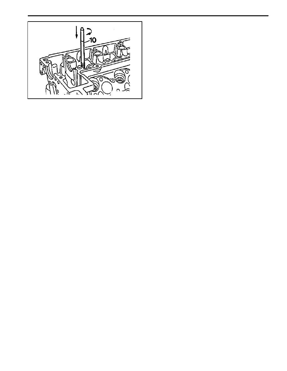
9. If necessary, ream the valve guide bore evenly.
Notice
Never turn the reamer against the direction of rota-
tion.
Reamer (for Exhaust) 000 589 10 53 00
Reamer (for Intake) 000 589 21 53 00
1B3 -- 122 OM600 ENGINE MECHANICAL
DAEWOO MY_2000
VALVE SEAT RINGS
Preceding Work : Removal of valve
Checking of valve guide, replace if necessary
Removal of prechamber
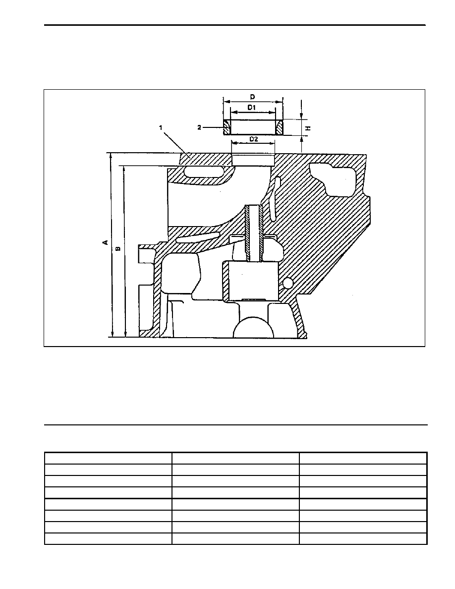
1 Cylinder Head
2 Valve Seat Ring
3 Valve Guide
A Height (Cylinder Head Upper / Lower Surface)
B Height (cylinder Head Cover Surface -- Seat of
Valve Seat Ring)
D
Valve Seat Ring Outer Diameter
D1 Valve Seat Ring Inner Diameter
D2 Basic Bore Diameter
H
Height of Valve Seat Ring
Service Ddata
Item
Intake
Exhaust
D2
40.000 -- 40.016 mm
37.000 -- 37.016 mm
D
40.084 -- 40.100 mm
37.084 -- 37.100 mm
D1
33.400 -- 33.600 mm
30.400 -- 30.600 mm
H
6.955 -- 7.045 mm
6.955 -- 7.045 mm
Overlap U=D--D2
0.068 -- 0.100 mm
0.068 -- 0.100 mm
B
133.4 mm
133.4 mm
A
142.5 mm
142.5 mm
OM600 ENGINE MECHANICAL 1B3 -- 123
DAEWOO MY_2000
Commercial Tools
Cylinder Head Clamping Device
Hunger
D--8000 München 70
Type Ventilknecht K2000
Order No. 221 00 100
Valve Seat Turning Tool
Hunger
D--8000 München 70
Type VDS 1A
Order No. 236 03 308
Ring Seat Turning Tool
Hunger
D--8000 München 70
Type RDS 1
Order No. 219 00 100
Pneumatic Removal / Installation Device
(Drift : 8mm, 9mm, 14mm)
Hunger
D--8000 München 70
Type PVM 1
Tensioning Head
Hunger
D--8000 München 70
Order No. 250 15 250
Cutting Tool for Recessing Grooves
Hunger
D--8000 München 70
Order No. 217 93 601
Test Set for Valves
Hunger
D--8000 München 70
Order No. 216 69 210
Internal Dial Gauge (Range : 25 -- 60mm)
Mahr
D--7300 Esslingen
Order No. 844
External Micrometer (Range : 25 -- 60mm)
Mahr
D--7300 Esslingen
Order No. 40 S
Electrically Heated Water Tank
Otto Dürr
D--7123 Sachsenherm -- Ochsenbach
1B3 -- 124 OM600 ENGINE MECHANICAL
DAEWOO MY_2000
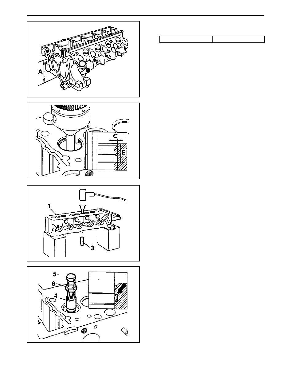
Removal Procedure
1. Measure dimension ’A’.
Limit
142.5 mm
2. Clamp the cylinder head with clamping device.
3. Cut groove into the valve seat ring so that dimension
’C’ is approx. 2mm and dimension ’E’ is approx.
6mm.
4. Remove the cylinder head from the clamping device
and place it onto wooden blocks.
5. Remove the valve guide (3).
Drift (Intake) 8mm
Drift (Exhaust) 9mm
6. Insert the tensioning head (4) and extracted wedges
(arrow) by turning the bolt (5).
Notice
Carefully tighten the bolt (5) otherwise the valve
seat ring in the cylinder headwill be excessively ten-
sioned.
7. Lock the bolt (5) with nut (6).
Нет комментариевНе стесняйтесь поделиться с нами вашим ценным мнением.
Текст