SsangYong Korando II (1996-2006 year). Manual — part 167

OM600 ENGINE MECHANICAL 1B3 -- 117
DAEWOO MY_2000
Notice
Measure center (arrow) of the valve guide and if the
inner diameter ’A’ exceeds standard value, replace
the guide.
Tools Required
000 589 10 53 00 Reamer (for Exhaust)
000 589 10 68 00 Cylinder Brush
000 589 21 53 00 Reamer (for Intake)
102 589 00 23 00 GO / NO GO Gauge (for Intake)
103 589 02 15 00 Drift (for Exhaust)
103 589 03 15 00 Drift (for Intake)
117 589 03 25 00 GO / NO GO Gauge (for Exhaust)
346 589 00 63 00 Super Cooling Box
601 589 02 23 00 GO/NO GO Gauge
601 589 05 15 00 Drift (for Intake)
601 589 06 15 00 Drift (for Exhaust)
Matching Valve Seat - Broaching Tools - Guide Sleeves
Valve Seat
Broaching Tool No.
Guide Sleeve Tool No.
Guide Sleeve Side
Intake
115 589 00 53 00
102 589 00 63 00
B
Exhaust
115 589 00 53 00
(14.2 mm)
102 589 00 63 00
102 589 08 63 00
B
Intake
115 589 01 53 00
601 589 15 63 00
A
Exhaust
115 589 01 53 00
(14.4 mm)
601 589 15 63 00
B
1B3 -- 118 OM600 ENGINE MECHANICAL
DAEWOO MY_2000
Checking
1. Thoroughly clean the valve guide bore using a cylin-
der brush.
Cylinder Brush 000 589 10 68 00
2. Insert the GO/NO GO gauge into the valve guide
bore. If the NO GO side is inserted fully, replace the
valve guide (Intake 8mm, Exhaust 9mm).
GO/NO GO Gauge 601 589 02 23 00
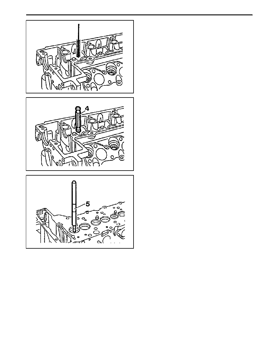
Replacement Procedure
1. Drive out the valve guide (2) by using a drift (5).
Notice
The valve guide must be driven out upward of the
cylinder head.
Drift (for Intake) 103 589 03 15 00
Drift (for Exhaust) 103 589 02 15 00
2. Thoroughly clean the basic bore by using a cylinder
brush.
Cylinder Brush 000 589 10 68 00
3. Check the basic bore in cylinder head for scoring
marks and ream to next repair size if necessary.

OM600 ENGINE MECHANICAL 1B3 -- 119
DAEWOO MY_2000
4. Reaming basic bore in cylinder head (repair size).
-- Thoroughly remove carbon deposits in cylinder
head.
Notice
Particularly remove the insides of the valve seat
rings.
-- Remove the elevation (arrow) of intake valve seat
rings.
-- Select correct broaching tool and guide sleeve
(refer to the table).
Notice
Before broaching work, the broaching tool must be
cleared of swarf with a stiff plastic brush.
-- Lubricate the basic bore, guide sleeve and
broaching tool with petroleum.
-- Push broaching tool (6) in broaching direction (ar-
row) into the guide sleeve (7) far enough so that
the first cut of the broaching tool is positioned in
the basic bore when guide sleeve is fitted onto
the valve seat ring (3).
6. Broaching tool
7. Guide sleeve
See the ’standard data’
-- Center the guide sleeve (7) in the valve seat ring
(3) by turning.
-- Knock through the broaching tool (6) with a plas-
tic hammer (approx. 25g). and aluminum drift.

1B3 -- 120 OM600 ENGINE MECHANICAL
DAEWOO MY_2000
5. Heat the cylinder head (1) in a wear tank to approx.
80_C.
6. Cool down the new valve guide (2) with liquid nitro-
gen.
Notice
Do not touch the cooled valve guide by hand.
Super Cooling box 346 589 00 63 00
7. Drive in new valve guide with drift (8) until the wire
ring makes contact.
Notice
The valve guide must be driven in from the cylinder
head cover.
Drift (for Intake) 601 589 05 15 00
Drift (for Exhaust) 601 589 06 15 00
8. Check the valve guide bore with GO / NO GO gauge
(9).
The GO side (marked ’0’) should just still drop. If the
GO side cannot be inserted, the bore of valve guide
should be reamed.
Notice
Perform the check only on cooled down cylinder
head.
GO / NO GO Gauge (for Intake) 102 589 00 23 00
GO / NO GO Gauge (for Exhaust) 117 589 03 23 00
Нет комментариевНе стесняйтесь поделиться с нами вашим ценным мнением.
Текст