SsangYong Korando II (1996-2006 year). Manual — part 239

SSANGYONG MY2002
4D-4 FRONT BRAKES
YAD4B080
CALIPER ASSEMBLY
Front Caliper Brake
1 Brake Caliper Assembly
2 Guide Rod Set
3 Brake Pad
4 Brake Pad Spring
5 Caliper Mounting Bolt
6 Piston Seal
7 Piston
8 Piston Boot
9 Caliper Guide Rod Bolt
10 Bleeder Screw
FRONT BRAKES 4D-5
SSANGYONG MY2002
;;;;
;;;;
;;;;
;;;;
;;;;
;;;;
yyyy
yyyy
yyyy
yyyy
yyyy
yyyy
;;;;;
;;;;;
;;;;;
;;;;;
;;;;;
;;;;;
;;;;;
yyyyy
yyyyy
yyyyy
yyyyy
yyyyy
yyyyy
yyyyy
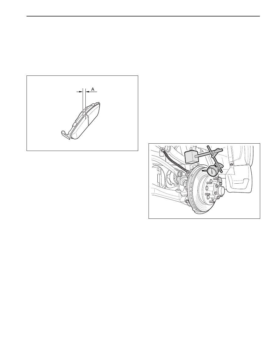
DIAGNOSTIC INFORMATION AND PROCEDURES
KAA4D020
PAD INSPECTION
1. Raise and suitably support the vehicle.
2. Remove the front wheel. Refer to Section 2E, Tires
and Wheels.
3. Visually check the linings for minimum thickness
and wear.
4. Measure the thickness.
Important: The minimum discard thickness of the
lining is 2 mm (0.08 inch).
5. Install the pads in axle sets only.
6. Install the rear wheels. Refer to Section 2E, Tires
and Wheels.
7. Lower the vehicle.
FRONT DISC BRAKE ROTOR
INSPECTION
Thickness variation can be checked by measuring the
thickness of the rotor at four or more points around the
circumference of the rotor. All measurements must be
made at the same distance in from the edge of the
rotor.
A rotor that varied by more than 0.013 mm (0.0005
inch) can cause pedal pulsations and/or front end
vibration during brake applications. A rotor that does
not meet these specifications should be refinished to
specifications or replaced.
During manufacturing, the brake rotor and the toler-
ances of the braking surface regarding flatness, thick-
ness variation, and lateral runout are held very close.
The maintenance of close tolerances on the shape of
the braking surfaces is necessary to prevent brake
roughness.
In addition to these tolerances, the surface finish must
be held to a specified range. The control of the braking
surface finish is necessary to avoid pulls and erratic
performance and to extend lining life.
Light scoring of the rotor surfaces not exceeding 0.4
mm (0.016 inch) in depth, which may result from normal
use, is not detrimental to brake operation.
Using a commercially available dial indicator, check
lateral runout as follows:
Notice: Permissible lateral runout is a maximum 0.07
mm (0.003 inch). If lateral runout exceeds the specifica-
tion, ensure that there is no dirt between the rotor and
the hub and that contact surfaces are smooth and free
from burrs.
1. Position the transaxle in NEUTRAL.
2. Remove the rotor. Refer to “Rotor” in this section.
3. Fasten the brake rotor to the wheel hub with two
wheel nuts. Refer to Section 2E, Tires and Wheels.
KAA4D030
4. Fasten a dial indicator to the brake caliper.
5. Set the gauge probe tip to approximately 10 mm
(0.394 inch) from the outer edge of the brake rotor,
perpendicular to the disc and under slight preload.
6. Remove the dial indicator and the wheel nuts that
connect the rotor to the hub.
Important: Since accurate control of the tolerances
is necessary for proper performance of the disc
brakes, refinishing of the rotor should be done only
with precision equipment.
7. Refinish the rotor, if required, with precision equip-
ment. Discard the rotor if it fails to meet the above
specifications after refinishing.
8. Install the rotor. Refer to “Rotor” in this section.
SSANGYONG MY2002
4D-6 FRONT BRAKES
KAA4D080
FRONT DISC BRAKE ROTOR
Removal and Installation Procedure
1. Raise and suitably support the vehicle.
2. Remove the front wheels. Refer to Section 2E,
Tires and Wheels.
3. Remove the hub bearing assembly. Refer to
Section 2C, Front Suspension.
4. Remove the front disc brake rotor.
5. Installation should follow the removal procedure in
the reverse order.
KAA4D040
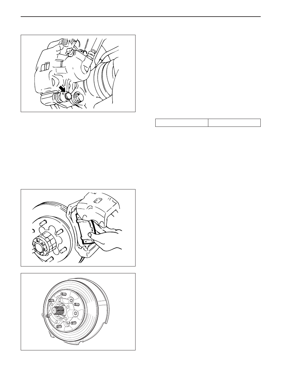
REPAIR INSTRUCTIONS
ON-VEHICLE SERVICE
BRAKE PADS
Removal and Installation Procedure
1. Raise and suitably support the vehicle.
2. Remove the front wheels. Refer to Section 2E,
Tires and Wheels.
3. Remove the caliper guide lower bolt.
Important: Caliper assembly removal is not
necessary to service the brake pad.
Installation Notice
•
Take care not to damage the piston seal when
the retaining frame is pulled down.
Tightening Torque
31 N•m (23 lb-ft)
KAA4D050
4. Remove the brake pads.
Installation Notice:
•
Measure the minimum brake pad thickness.
Refer to “Lining Inspection” in this section.
•
Always change the all pads on one wheel at a
time.
5. Installation should follow the removal procedure in
the reverse order.

FRONT BRAKES 4D-7
SSANGYONG MY2002
KAA4D060
KAA4D070
CALIPER ASSEMBLY
Removal and Installation Procedure
1. Raise and suitably support the vehicle.
2. Remove the front wheels. Refer to Section 2E,
Tires and Wheels.
3. Remove the brake hose mounting nut and
disconnect the hose. Plug the openings in the
caliper and the brake hose to prevent fluid loss
and contamination.
Installation Notice
Tightening Torque
30 N•m (22 lb-ft)
4. Remove the caliper mounting bolts and then
remove the caliper assembly.
Installation Notice
Tightening Torque
95 N•m (70 lb-ft)
•
Bleed the caliper. Refer to Section 4A, Hydraulic
Brakes.
Notice: do not move the vehicle until a firm pedal
is obtained or improper braking action will result.
•
Repeatedly press the brake pedal to bring the
pads in contact with the rotor.
5. Installation should follow the removal procedure
in the reverse order.
SPLASH SHIELD
Removal and Installation Procedure
1. Raise and suitably support the vehicle.
2. Remove the front wheels. Refer to Section 2E,
Tires and Wheels.
3. Remove the hub bearing assembly. Refer to
Section 2C, Front Suspension.
4. Remove the front disc brake rotor. Refer to “Front
Disc Brake Rotor” in this section.
5. Remove the splash shield bolt.
Installation Notice
KAA4D090
Tightening Torque
6 N•m (53 lb-ft)
6. Installation should follow the removal procedure
in the reverse order.
Нет комментариевНе стесняйтесь поделиться с нами вашим ценным мнением.
Текст