SsangYong Korando II (1996-2006 year). Manual — part 261

ABS AND TCS 4F-59
SSANGYONG MY2002
Step
1
2
3
4
5
6
7
DTC 42 - Acceleration Sensor Fault
Action
Go to Step 3
Go to Step 5
System OK
System OK
Go to Step 7
System OK
System OK
Go to Step 2
Go to Step 4
-
-
Go to Step 6
-
-
-
4.75 - 5.25 v
-
-
1.95 - 3.45 v
-
-
Examine the acceleration sensor.
Are there any signs of physical damage?
1. Turn the ignition switch to ON.
2. Use a digital voltmeter (DVM) to measure the
voltage between terminal 39 and 43 of EBCM.
Is the voltage within the specified value?
Replace the acceleration sensor.
Is the repair complete?
Repair the open in the affected circuit or replace the
acceleration sensor, if necessary.
Is the repair complete?
1. Place the acceleration sensor horizontally and let
the acceleration sensor
2. Turn the ignition switch to ON.
3. Use a digital voltmeter (DVM) to measure the
voltage between terminal 39 and 51 of EBCM.
Is the voltage within the specified value?
Repair the open in the affected circuit or replace the
acceleration sensor, if necessary.
Is the repair complete?
Replace the ABS unit.
Is the repair complete?
Value(s)
Yes
No

SSANGYONG MY2002
4F-60 ABS AND TCS
DIAGNOSTIC TROUBLE CODE (DTC) 43
ACCELERATION SENSOR CONTINUITY FAULT
KAA4F190
Circuit Description
The acceleration sensor provides a voltage signal that
changes in relation to the acceleration of vehicle. The
signal voltage will vary from about 1.95 to 3.45 volt.
The electronic brake control module (EBCM) monitor a
signal voltage of deceleration in the vehicle.
Diagnosis
This procedure checks for a malfunctioning acceleration
sensor, a short to ground or to voltage in the wiring, or
a contact problem in a connector.
Cause
•
The vertical acceleration sensor is defective or dis
connected
•
There is a problem in the wiring
•
There is a problem with a connector
•
Wrong installed vertical acceleration sensor
Fail Action
ABS action is disabled, and the ABS warning lamp is
ON.
Test Description
The number(s) below refer to step(s) on the diagnostic
table.
2. This step checks for the voltage reference from
the EBCM.
5. This step checks for the voltage signal from the
acceleration sensor.
Diagnostic Aids
Be sure that the acceleration sensor wiring is properly
routed and retained.
It is very important to perform a thorough inspection of
the wiring and the connectors carefully and completely
may result in misdiagnosis, causing part replacement
with the reappearance of the malfunction.
You can use the scan tool to monitor acceleration sensor
during a road test. Watch the acceleration sensor being
displayed on the scan tool to see if any of the reading
is unusual.

ABS AND TCS 4F-61
SSANGYONG MY2002
Step
1
2
3
4
5
6
7
DTC 43 - Acceleration Sensor Continuity Fault
Action
Go to Step 3
Go to Step 5
System OK
System OK
Go to Step 7
System OK
System OK
Go to Step 2
Go to Step 4
-
-
Go to Step 6
-
-
-
4.75 - 5.25 v
-
-
1.95 - 3.45 v
-
-
Examine the acceleration sensor.
Are there any signs of physical damage?
1. Turn the ignition switch to ON.
2. Use a digital voltmeter (DVM) to measure the
voltage between terminal 39 and 43 of EBCM.
Is the voltage within the specified value?
Replace the acceleration sensor.
Is the repair complete?
Repair the open in the affected circuit or replace the
acceleration sensor, if necessary.
Is the repair complete?
1. Place the acceleration sensor horizontally and let
the acceleration sensor
2. Turn the ignition switch to ON.
3. Use a digital voltmeter (DVM) to measure the
voltage between terminal 39 and 51 of EBCM.
Is the voltage within the specified value?
Repair the open in the affected circuit or replace the
acceleration sensor, if necessary.
Is the repair complete?
Replace the ABS unit.
Is the repair complete?
Value(s)
Yes
No
SSANGYONG MY2002
4F-62 ABS AND TCS
DIAGNOSTIC TROUBLE CODE (DTC) 13/14
LEFT FRONT INLET AND OUTLET VALVE SOLENOID FAULT
KAA4F200
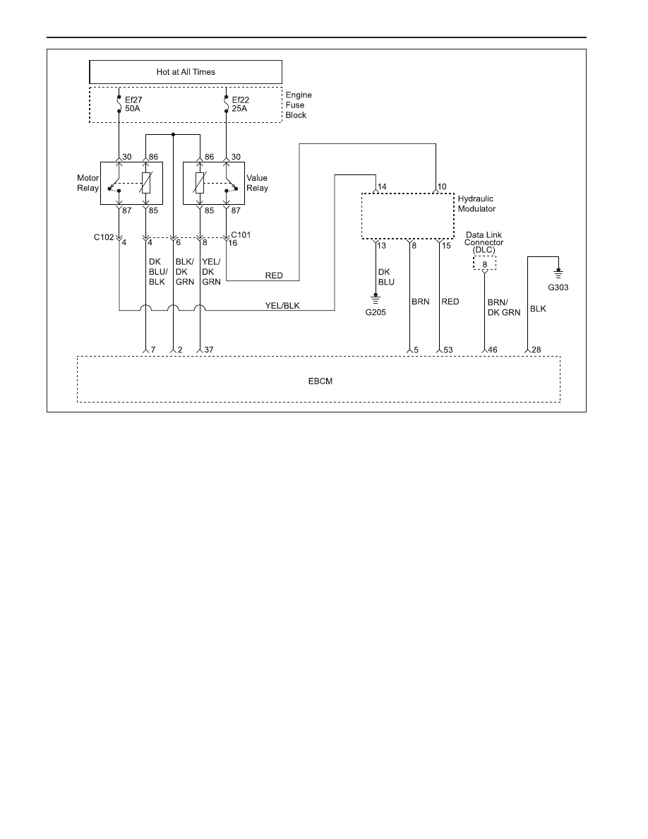
Circuit Description
The solenoid valve coil circuits are supplied with power
from the battery when the valve relay is energized.
Switched ground is provided by the electronic brake
control module (EBCM) to each coil.
Diagnosis
This procedure checks whether the left front inlet and
outlet valves are functioning.
Cause(s)
•
A valve has failed.
•
A solenoid coil is open or shorted.
Fail Action
ABS is disabled, and the ABS warning lamp is turned
ON for the remainder of the ignition cycle. If the failure
is intermittent, the EBCM will enable the system at the
next ignition cycle and set a history DTC.
Test Description
The number(s) below refer to step(s) on the diagnostic
table.
1. This step begins the test of the inlet valve.
3. This step tests the outlet valve.
Нет комментариевНе стесняйтесь поделиться с нами вашим ценным мнением.
Текст