SsangYong Korando II (1996-2006 year). Manual — part 130

1F2 -- 100 M161 ENGINE CONTROLS
DAEWOO MY_2000
YAA1F770
Notice: Before removal, the fuel rail assembly may be
cleaned with a spray-type cleaner, following package in-
structions. Do not immerse the fuel rails in liquid clean-
ing solvent. Use care in removing the fuel rail assembly
to prevent damage to the electrical connectors and in-
jector spray tips. Prevent dirt and other contaminants
from entering open lines and passages. Fittings should
be capped and holes plugged during service.
Important: If an injector becomes separated from the
rail and remains in the cylinder head, replace the injector
O-ring seals and the retaining clip.
12. Remove the injectors and the fuel rail carefully.
13. Remove the fuel injector retainer clips.
14. Remove the fuel injectors by pulling them down and
out.
15. Discard the fuel injector O-rings.
16. Lubricate the new fuel injector O-rings with engine
oil. Install the new O-rings on the fuel injectors.
17. Perform a leak check of the fuel rail and fuel injec-
tors.
18. Installation should follow the removal procedure in
the reverse order.
YAA1F780
ENGINE COOLANT TEMPERATURE
SENSOR
Removal and Installation Procedure
1. Relieve the coolant system pressure.
2. Disconnect the negative battery cable.
3. Disconnect the engine coolant temperature sensor
connector.
Notice: Take care when handling the engine coolant
temperature sensor. Damage to the sensor will affect
the proper operation of the fuel injection system.
4. Remove the engine coolant temperature sensor
from the pump hosing.
Installation Notice
Tightening Torque
30 NSm (22 Ib-ft)
5. Installation should follow the removal procedure in
the reverse order.
M161 ENGINE CONTROLS 1F2 -- 101
DAEWOO MY_2000
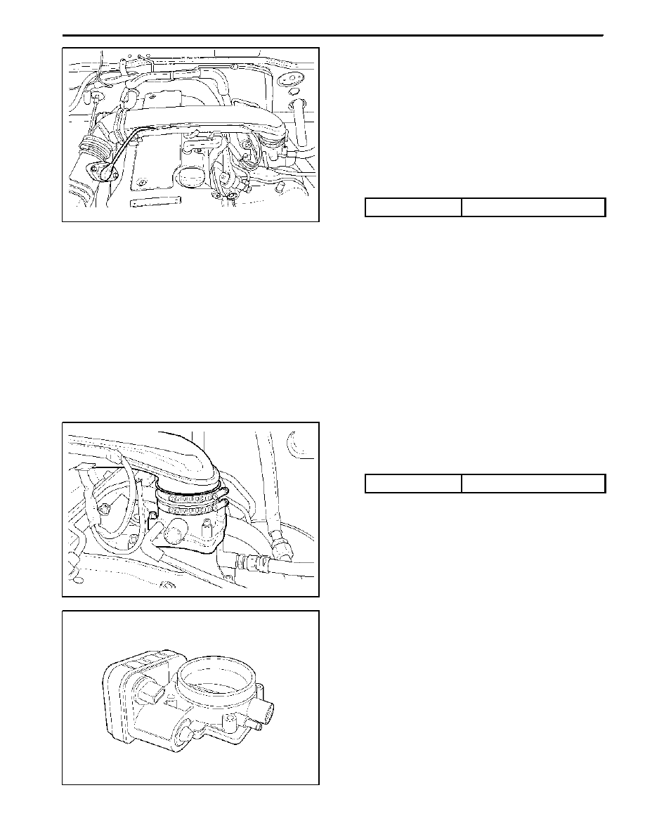
YAA1F740
THROTTLE BODY (INTEGRATED
WITH THE ACTUATOR)
Removal and Installation Procedure
1. Disconnect the negative battery cable.
2. Disconnect the mass air flow sensor connector.
3. Disconnect the mass air flow sensor from the air fil-
ter housing.
4. Remove the intake air duct mounting bolts.
Installation Notice
Tightening Torque
9 NSm (80 lb-in)
5. Remove the air inlet housing clamps.
6. Remove the inlet air housing.
YAA1F790
7. Disconnect the throttle body electrical connector.
8. Remove the throttle body bolts.
Installation Notice
Tightening Torque
12 NSm (106 lb-in)
9. Remove the vacuum hose.
KAA1D240
10. Remove the throttle body and discard the gasket.
Important: Use care in cleaning old gasket material.
Sharp tools may damage sealing surfaces.
11. Installation should follow the removal procedure in
the reverse order.
1F2 -- 102 M161 ENGINE CONTROLS
DAEWOO MY_2000
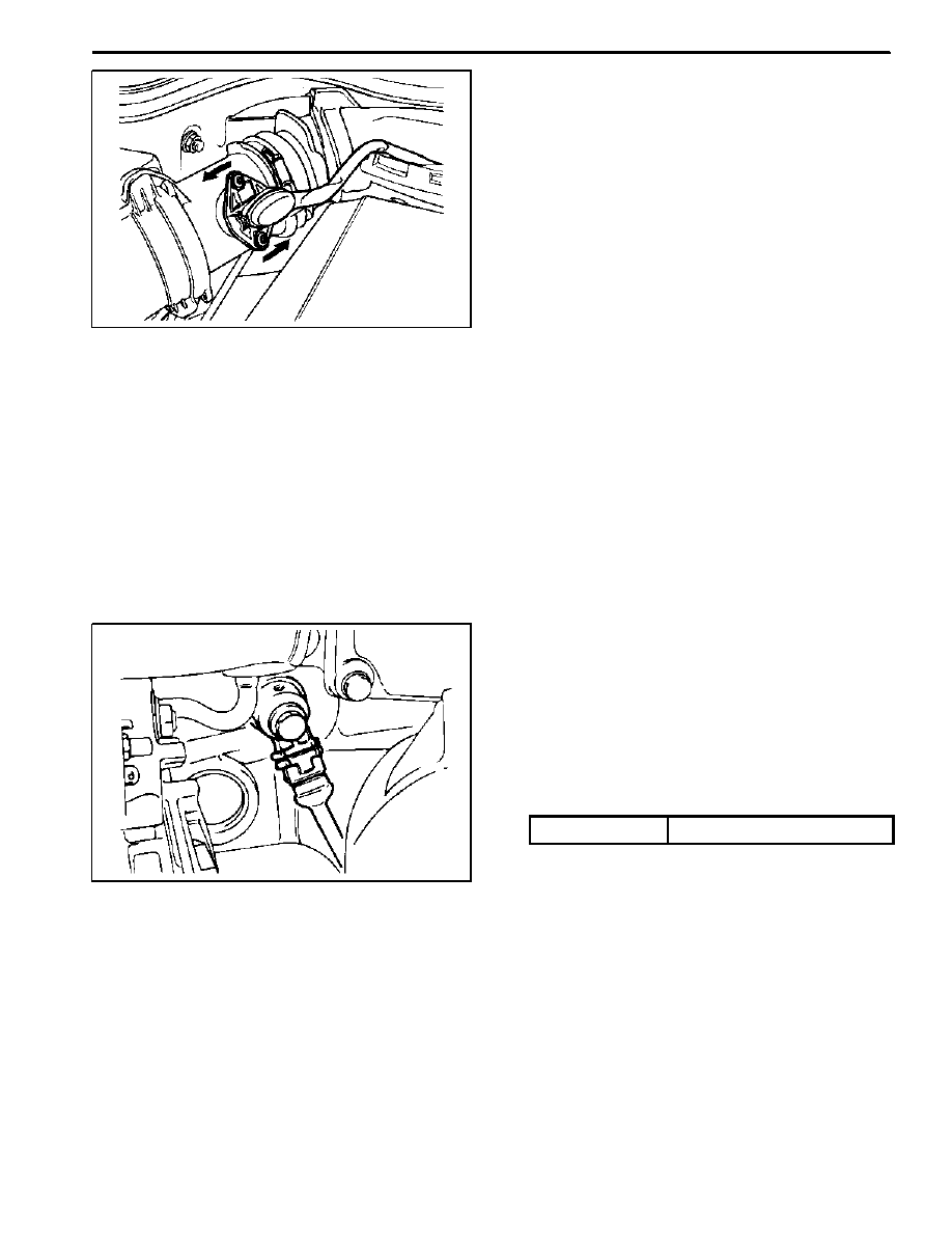
KAA1F190
HOT FILM AIR MASS (HFM) SENSOR
Removal and Installation Procedure
1. Disconnect the negative battery cable.
2. Disconnect the Hot Film Air Mass (HFM) sensor
electrical connector.
3. Remove the HFM sensor retaining screws.
4. Turn the HFM sensor coupling in the direction
shown in the figure in the left so that it gets sepa-
rated from the contact surface.
Notice: Make sure the HFM sensor coupling connects
completely with the contact surface installation.
5. Remove the HFM sensor.
6. Installation should follow the removal procedure in
the reverse order.
KAA1F180
KNOCK SENSOR
Removal and installation Procedure
1. Disconnect the negative battery cable.
2. Disconnect the knock sensor electrical connector
from the intake manifold bracket.
3. Remove the knock sensor mounting bolt from the
knock sensor installed on the cylinder block.
Installation Notice
Tightening Torque
25 NSm (18 Ib-ft)
4. Remove the knock sensor.
5. Installation should follow the removal procedure in
the reverse order.
M161 ENGINE CONTROLS 1F2 -- 103
DAEWOO MY_2000
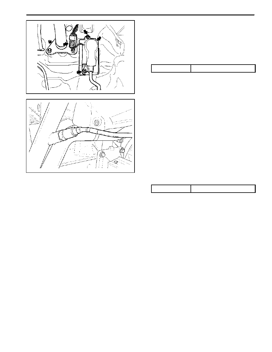
KAA1F410
PEDAL POSITION SENSOR
Removal and installation Procedure
1. Disconnect the negative battery cable.
2. Disconnect the pedal position sensor connector.
3. Unscrew the bolts and nut.
Installation Notice
Tightening Torque
6 NSm (53 lb-in)
4. Remove the pedal and sensor assembly.
5. Installation should follow the removal procedure in
the reverse order.
YAA1F820
OXYGEN SENSOR
Removal and Installation Procedure
1. Disconnect the negative battery cable.
Notice: The oxygen sensor uses a permanently at-
tached pigtail and connector. This pigtail should not be
removed from the oxygen sensor. Damage or removal
of the pigtail or the connector could affect proper opera-
tion of the oxygen sensor. Do not drop the oxygen sen-
sor.
2. Disconnect the electrical connector.
3. Carefully remove the oxygen sensor from the exhaust
pipe.
Installation Notice
Tightening Torque
55 NSm (41 Ib-ft)
Important: A special anti-seize compound is used on
the oxygen sensor threads. This compound consists of
a liquid graphite and glass beads. The graphite will burn
away, but the glass beads will remain, making the sen-
sor easier to remove. New or serviced sensors will al-
ready have the compound applied to the threads. If a
sensor is removed from any engine and is to be rein-
stalled, the threads must have an anti-seize compound
applied before reinstallation.
4. Coat the threads of the oxygen sensor with an anti-
seize compound, if needed.
5. Installation should follow the removal procedure in
the reverse order.
Нет комментариевНе стесняйтесь поделиться с нами вашим ценным мнением.
Текст