SsangYong Korando II (1996-2006 year). Manual — part 131

1F2 -- 104 M161 ENGINE CONTROLS
DAEWOO MY_2000
KAB1F400
PURGE CONTROL VALVE
Removal and Installation Procedure
1. Disconnect the negative battery cable.
2. Disconnect the purge control valve connector.
3. Disconnect the throttle body-to-purge control valve
hose from the purge control valve.
4. Disconnect the canister-to-purge control valve hose
from the purge control valve.
5. Remove the purge control valve.
6. Installation should follow the removal provedure in
the reverse order.
KAB1F410
CANISTER
Removal and Installation Procedure
Caution: Canister and vacuum hoses contain fuel
vapors. Do not smoke in the area or permit an open
flame.
1. Disconnect the fuel tank-to-canister hose form the
canister.
2. Disconnect the canister-to-purge control valve hose
form the canister.
KAB1F400
3. Remove the canister mounting bolts.
Installation Notice
Tightening Torque
6 NSm (53 lb-in)
4. Remove the canister.
5. Installation should follow the removal procedure in
the reverse order.
YAA1F810
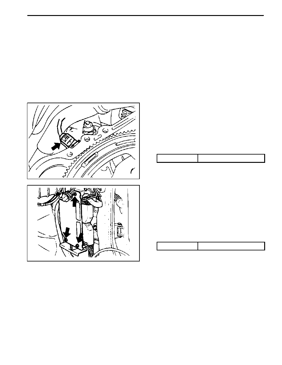
CAMSHAFT POSITION SENSOR
Removal and Installation Procedure
1. Disconnect the negative battery cable.
2. Disconnect the electrical connector from the cam-
shaft position sensor.
3.Remove the camshaft position sensor retaining bolt.
Installation Notice
Tightening Torque
10 NSm (89 Ib-in)
M161 ENGINE CONTROLS 1F2 -- 105
DAEWOO MY_2000
4. Check the O-ring for damage and replace it if neces-
sary.
5. Installation should follow the removal procedure in
the reverse order.
KAA1F160
CRANKSHAFT POSITION SENSOR
Removal and installation Procedure
1. Disconnect the negative battery cable.
2. Disconnect the electrical connector at the crankshaft
position sensor.
3. Remove the crankshaft position sensor retaining bolt.
Installation Notice
Tightening Torque
10 NSm (89 lb-in)
4. Installation should follow the removal procedure in
the reverse order.
KAA1F200
ENGINE CONTROL MODULE
Removal and installation Procedure
1. Disconnect the negative battery cable.
2. Remove the cowl side trim form passenger side. Re-
fer to Section 9G, Interior trim.
3. Remove the four securing nuts for the Engine Control
Module (ECM) from the mounting bracket.
Installation Notice
Tightening Torque
10 NSm (89 lb-in)
4. Pull out the ECM from the bracket.
5. Disconnect the vehicle side coupling.
6. Installation should follow the removal procedure in
the reverse order.
DAEWOO MY_2000
SECTION 1G2
M161 ENGINE INTAKE & EXHAUST
CAUTION: Disconnect the negative battery cable before removing or installing any electrical unit or when a
tool or equipment could easily come in contact with exposed electrical terminals. Disconnecting this cable
will help prevent personal injury and damage to the vehicle. The ignition must also be in LOCK unless other-
wise noted.
TABLE OF CONTENTS
Specifications
1G2--2
. . . . . . . . . . . . . . . . . . . . . . . . . . .
Fastener Tightening Specifications
1G2--2
. . . . . . . . .
Maintenance and Repair
1G2--3
. . . . . . . . . . . . . . . . . .
On--Vehicle Service
1G2--3
. . . . . . . . . . . . . . . . . . . . . . . .
Air Cleaner
1G2--3
. . . . . . . . . . . . . . . . . . . . . . . . . . . . .
Air Intake Shield
1G2--5
. . . . . . . . . . . . . . . . . . . . . . . . .
Intake Air Duct
1G2--6
. . . . . . . . . . . . . . . . . . . . . . . . . .
Intake Manifold
1G2--8
. . . . . . . . . . . . . . . . . . . . . . . . .
Exhaust Manifold
1G2--10
. . . . . . . . . . . . . . . . . . . . . . .
Removal and Installation of Exhaust
System
1G2--12
. . . . . . . . . . . . . . . . . . . . . . . . . . . . .

1G2 -- 2 M161 ENGINE INTAKE & EXHAUST
DAEWOO MY_2000
SPECIFICATIONS
FASTENER TIGHTENING SPECIFICATIONS
Application
NSm
Lb-Ft
Lb-In
Air Cleaner Mounting Bolt
22.5 -- 27.5
16.6 -- 20.3
--
Intake Manifold Mounting Bolts
22.5 -- 27.5
16.6 -- 20.3
--
Idle Regulator and Intermediate Flange Bolts
22.5 -- 27.5
16.6 -- 20.3
--
Supporting Assembly Bolts
22.5 -- 27.5
16.6 -- 20.3
--
Oxygen Sensor
55
41
--
Connection Piece
36 -- 44
27 -- 33
--
Exhaust Pipe Flange Bolts
30
22
--
Exhaust Manifold Nuts
31.5 -- 38.5
23.2 -- 28.4
--
Exhaust Pipe--to--Catalytic Converter Flange Nuts
28 -- 47
21 -- 35
--
Front Muffler Pipe--to--Catalytic Converter Flange Nuts
28 -- 47
21 -- 35
--
Rear Muffler Pipe Flange--to --Front Muffler Pipe Flange
Nuts
28 -- 47
21 -- 35
--
Нет комментариевНе стесняйтесь поделиться с нами вашим ценным мнением.
Текст