SsangYong Korando II (1996-2006 year). Manual — part 179
OM600 ENGINE MECHANICAL 1B3 -- 165
DAEWOO MY_2000
Removal Procedure
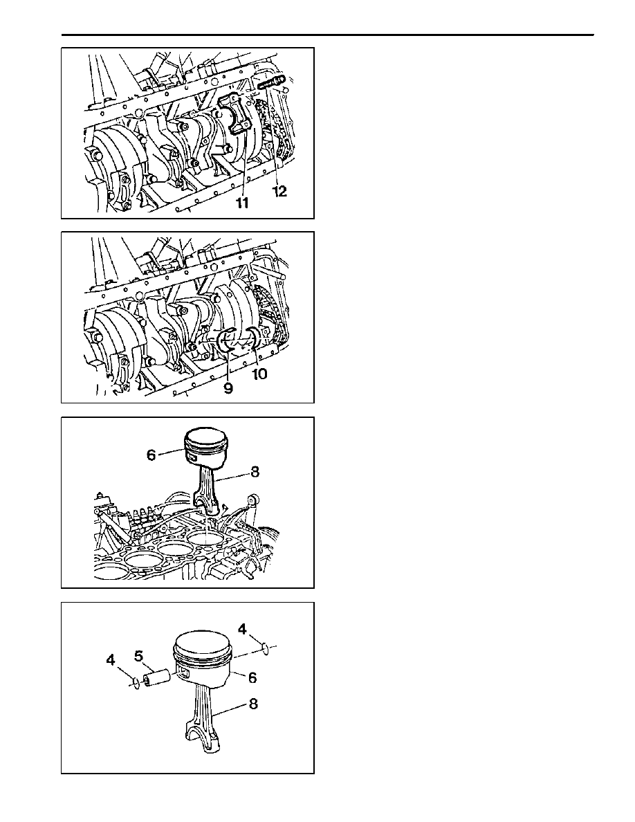
1. Remove combustion residues from the cylinder
bores.
2. Remove the connecting rod bolts (12) and then re-
move the connecting rod bearing caps(11).
3. Remove the connecting rod bearing shells (9, 10).
Notice
Be careful not mix the bearing caps and shells each
other.
4. Remove the piston (6) and connecting rod (8).
5. Remove the snap ring (4) and pull out the piston pin
(5).
6. Separate the piston and connecting rod.
1B3 -- 166 OM600 ENGINE MECHANICAL
DAEWOO MY_2000
Installation Procedure
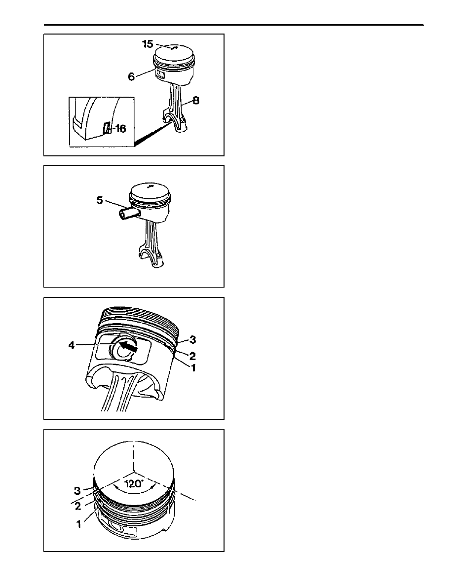
1. Fit the piston onto the connecting rod so that the ar-
row (15) and the locking slot (16) are facing in direc-
tion of the vehicle.
2. Coat the piston pin (15) with engine oil and insert it
by hand.
Notice
Do not heat up the piston.
3. Install the new snap ring (4) into the grooves (ar-
row).
4. Check the piston rings (1, 2, 3) and replace them if
necessary.
5. Install and arrange the piston rings to be evenly
120_ from each ends gap.
OM600 ENGINE MECHANICAL 1B3 -- 167
DAEWOO MY_2000
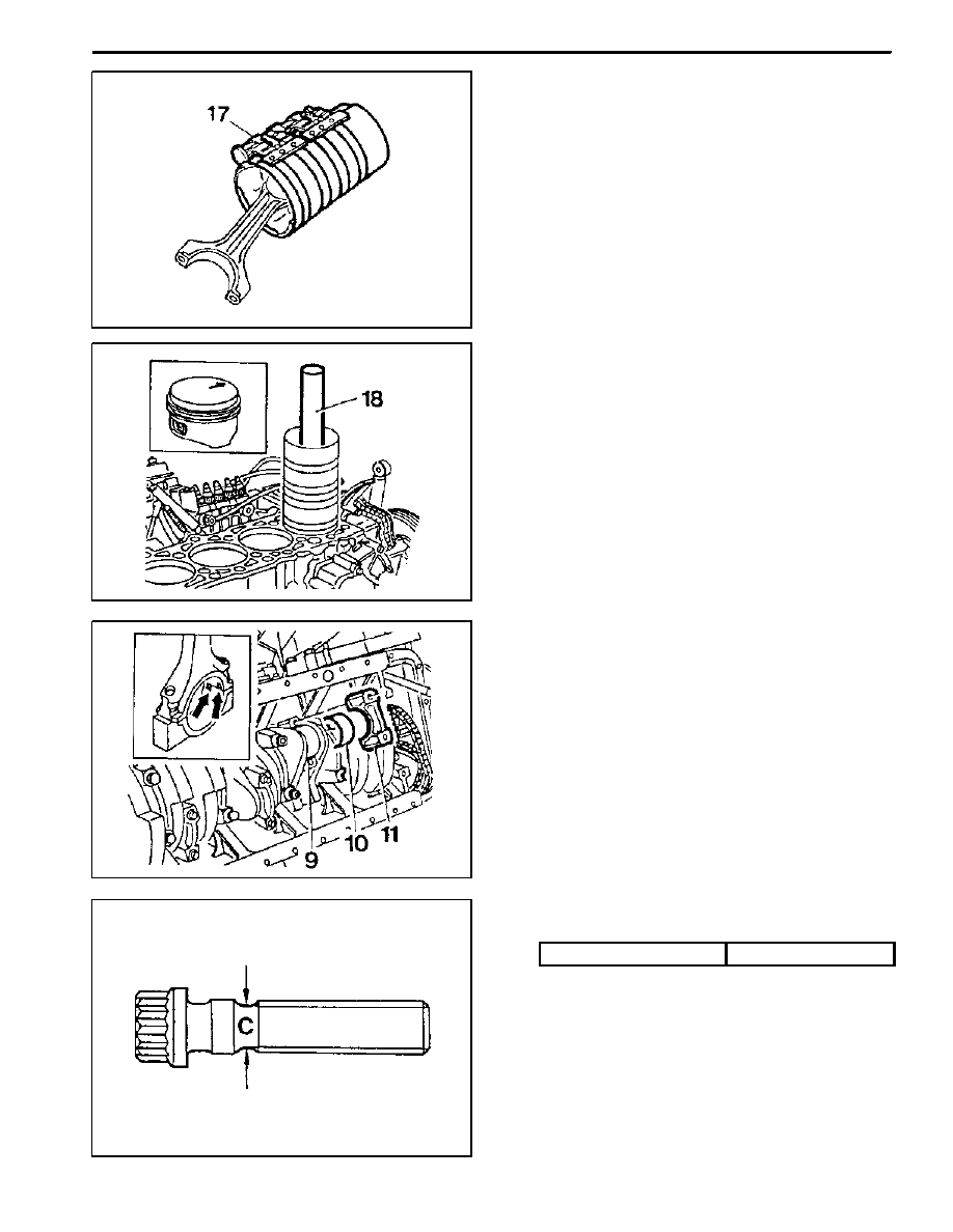
6. Coat the cylinder bore, connecting rod bearing jour-
nal, connecting rod bearing shell and piston with oil.
7. Compress the piston rings with a tensioning strap
(7).
Tensioning Strap 000 589 04 14 00
8. Insert the piston assembly into the cylinder with a
wooden stick (18).
Notice
The arrow on the piston crown must point toward the
front of vehicle.
9. Insert the connecting rod bearing shells (9, 10).
Notice
Be careful of the difference in upper and lower bear-
ing shells and not to be changed.
10. Position the connecting rod bearings caps.
Notice
Position so that the retaining lugs are on the same
side of the connecting rod bearing(arrow).
11. Measure stretch shaft diameter (C) of the connect-
ing rod bolts.
Limit ’C’
7.1mm
1B3 -- 168 OM600 ENGINE MECHANICAL
DAEWOO MY_2000
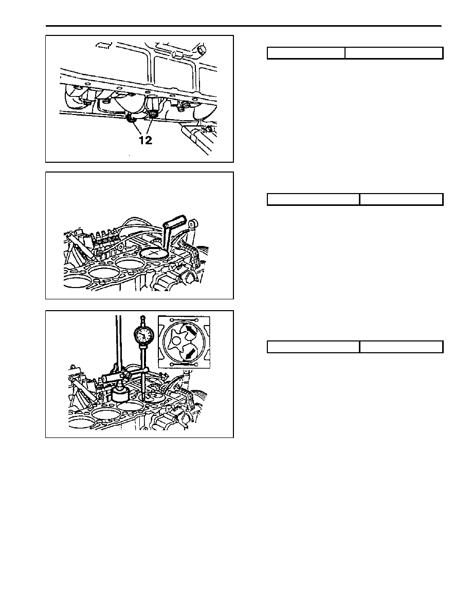
12. Coat the bolts (12) with oil and then tighten the bolts.
Tightening Torque
40 N∙m (30 lb-ft) + 90_
13. Rotate the crankshaft and check axial clearance be-
tween the connecting rod and crankshaft.
14. Measure clearance between the piston crown and
cylinder
Standard
Max. 0.12mm
15. Position the piston at TDC and measure the dis-
tance between the piston crown and the crankcase
surface.
Standard
Max. 0.965 mm
Notice
Measure at points marked.
Dial Gauge 001 589 00 53 21
Dial Gauge Holder 363 589 02 21 00
Нет комментариевНе стесняйтесь поделиться с нами вашим ценным мнением.
Текст