SsangYong Korando II (1996-2006 year). Manual — part 78
M161 ENGINE MECHANICAL 1B2 -- 17
DAEWOO MY_2000
Operation When Full- Load at Partial Load
D
The throttle valve (6) is partially opened or fully
opened.
The air flows very rapidly through the vent line (5) s
connection (D) and the intake air duct when full--load
at partial load.
Consequently, most of the low--by gases are supplied
to the combustion chamber through the timing gear
case cover (15), chain housing (17), oil separation
chamber (3), vent line (5), throttle valve (6), and in-
take manifold (8).

1B2 -- 18 M161 ENGINE MECHANICAL
DAEWOO MY_2000
GENERATOR
1 Bolt (M8 X 40, 3 pieces)
22.5--27.5 NSm (16.6--20.3 lb-ft)
. . . . . . . . . . . . .
2 Bolt (M8 X 70, 2 pieces)
22.5--27.5 NSm (16.6--20.3 lb-ft)
. . . . . . . . . . . . .
3 Bolt (M8 X 85, 1 piece)
22.5--27.5 NSm (16.6--20.3 lb-ft)
. . . . . . . . . . . . .
4 Generator Bracket
Removal & Installation Procedure
1. Disconnect the negative battery cable.
2. Remove the drive belt.
3. Remove the generator.
4. Unscrew the generator carrier bolts and remove the
carrier.
Installation Notice
Tightening Torque
25 NSm (18 lb-ft)
Notice: Apply 3 Nm of torque when mounting the bolt
(1) ; apply 25 Nm of torque when mounting the bolts (2),
and (3) ; and then tighten the bolt (1) with 25 Nm of
torque.
5. Installation should follow the removal procedure in
the reverse order.
M161 ENGINE MECHANICAL 1B2 -- 19
DAEWOO MY_2000
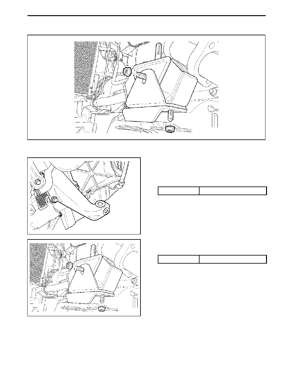
ENGINE MOUNT
Removal & Installation Procedure
1. Unscrew the upper engine mount nuts and remove
the engine.
Installation Notice
Tightening Torque
70 NSm (52 lb-ft)
2. Unscrew the lower nuts.
Installation Notice
Tightening Torque
38 NSm (28 lb-ft)
3. Remove the hydraulic engine mounting insulator.
4. Installation should follow the removal procedure in
the reverse order.

1B2 -- 20 M161 ENGINE MECHANICAL
DAEWOO MY_2000
POLY V -- BELT
Preceding Work: Removal of cooling fan
1 Poly V--belt (2,155 mm)
2 Belt Tensioning Pulley
3 Belt Tensioner
Removal & Installation Procedure
1. Release the belt tension by turning the stud on the
cap with 12 sided wrench or spanner counterclock-
wise.
2. Remove the poly v--belt.
Notice: Check the belt for damage and tensioning
pulley bearing point for wear and replace them if neces-
sary.
3. Install the belt after prying the tensioning pulley.
Нет комментариевНе стесняйтесь поделиться с нами вашим ценным мнением.
Текст