SsangYong Korando II (1996-2006 year). Manual — part 312
5A-158 AUTOMATIC TRANSMISSION
SSANGYONG MY2002
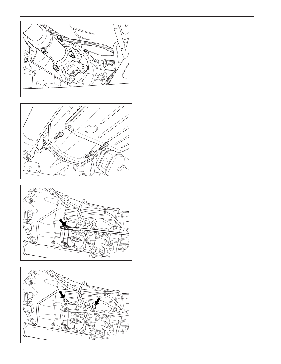
8. Remove the transfer case-to-transmission housing
bolts and remove the transfer case.
Installation Notice
10. Separate the locking clip on shift lever and remove
the shift rod.
Notice: Removal and installation performed when
the shift procedure should be lever is in ’D’ range.
11. Remove the oil cooler pipes.
Installation Notice
9. Disconnect the 10-Pins Plug connector from trans-
mission.
7. Remove the front propeller shaft bolts from transfer
case.
Installation Notice
KAA5A5V0
KAA5A2K0
KAA5A2L0
KAA5A2M0
Tightening Torque
70 - 80 N•m
(52 - 59 lb-ft)
Tightening Torque
35 - 60 N•m
(28 - 44 lb-ft)
Tightening Torque
40 - 45 N•m
(29 - 33 lb-ft)
AUTOMATIC TRANSMISSION 5A-159
SSANGYONG MY2002
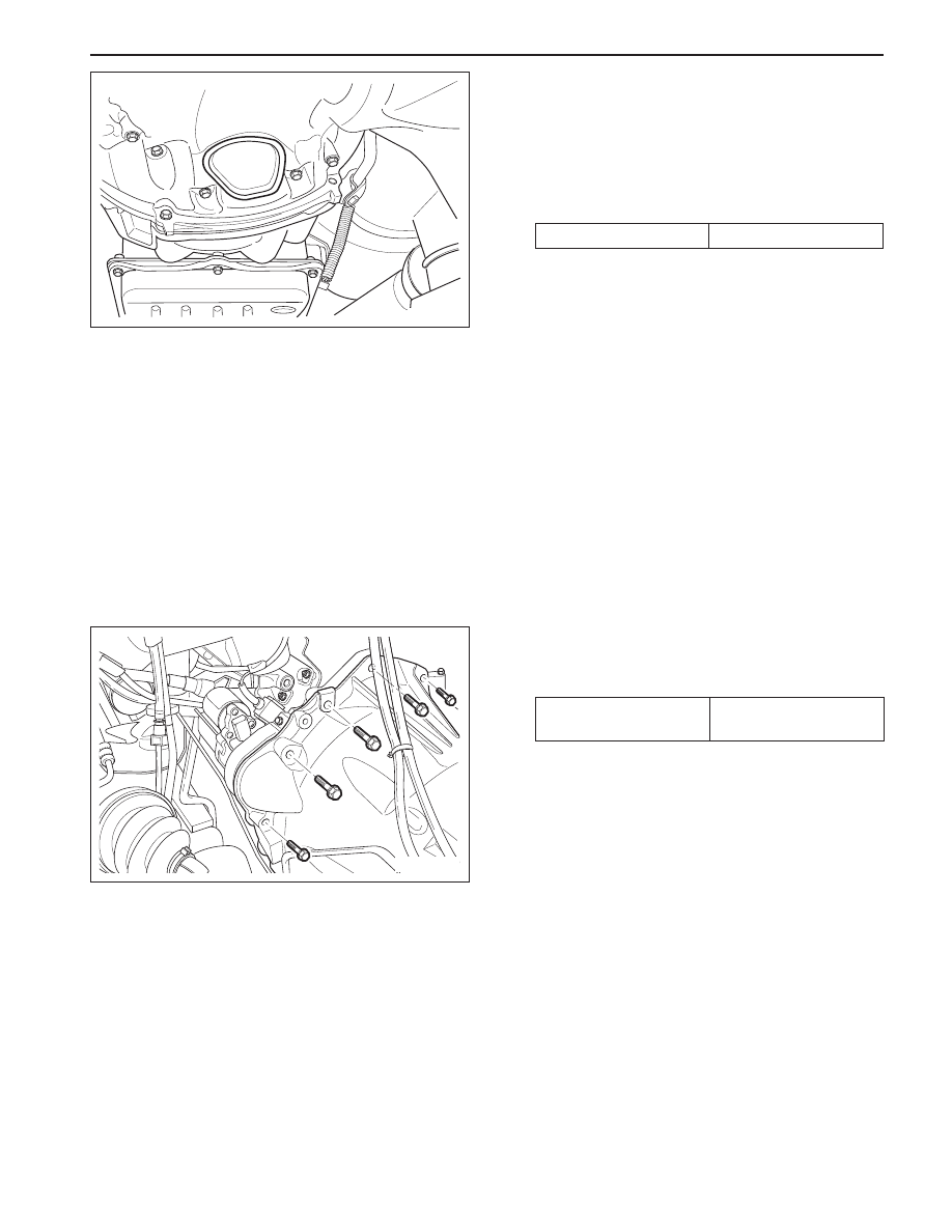
12. Remove the service hole cover in the engine block.
13. Put the alignment mark for installation, and
removethe six mounting bolts for torque converter
from drive plate through the service hole by
rotating the engine and remove the torque
converter.
Installation Notice
•
Screw the six bolts mounting the torque
converter through the service hole by using a
mirror and rotating the engine.
14. Remover the starter. Refer to Section 1E, Engine
Electrical.
15. Remove the extension housing to case bolts and
remove the transmission assembly.
Installation Notice
•
Be careful not to drop the torque converter while
removing the transmission.
16. Installation should follow the removal procedure
in the reverse order.
KAA5A2N0
KAA5A2O0
Tightening Torque
54 - 68 N•m
(40 - 50 lb-ft)
Tightening Torque
42 N•m (31 lb-ft)
5A-150 AUTOMATIC TRANSMISSION
SSANGYONG MY2002
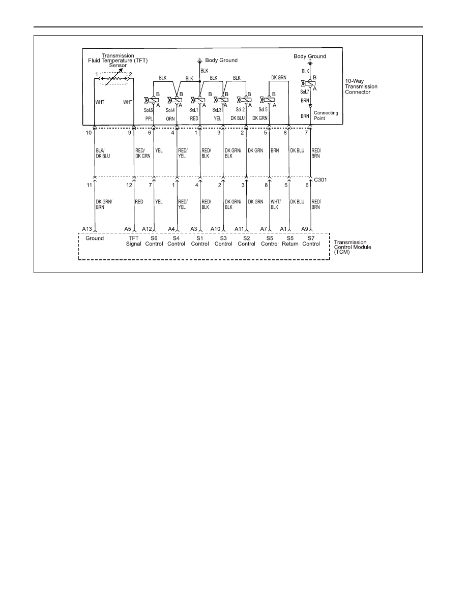
Circuit Description
The solenoid 6 is a normally open ON/OFF type sole-
noid that is used to set the high/ low level of line pres-
sure.
The solenoid 6 (S6) OFF gives high pressure and the
S 6 i s a t t a c h e d t o t h e v a l v e b o d y w i t h i n t h e
transmission. Voltage is supplied directly to the
solenoid through the Transmission Control Module
(TCM).
The DTC P1746 sets when the Solenoid 6 (S6) circuit
is shorted to ground. The solenoid 6’s driver
Integrated Chip (IC) status indicates a faulty circuit.
Conditions for Setting the DTC
•
DTCs P1717 and P1718 are not set.
•
S6 is ON.
•
The solenoid 6’s driver Integrated Chip (IC) status
indicates a faulty circuit. This condition must be
continuously present for 60 milliseconds.
Action Taken When the DTC Sets
•
The solenoid 6 is disabled (OFF) resulting in high
line pressure being applied continuously.
Conditions for Clearing the DTC
•
The DTC will clear when the malfunction has not
occurred after ignition cycle.
DIAGNOSTIC TROUBLE CODE (DTC) P1746
SOLENOID 6 CIRCUIT SHORT
•
A history DTC will clear after 40 TCM power-up
cycles with a warm transmission (>50 °C) and
without a fault.
•
History DTCs can be cleared by using a scan tool.
Diagnostic Aids
•
During the TCM’s testing, solenoid 6 is turned OFF/
ON by a very small (4 millisecond) pulses. This
pulse is too short for the solenoid to react so the
transmission operation is not affected.
•
The solenoid feedback voltage is measured before
the (4 millisecond) pulse and again during the
pulse. If the difference is outside the acceptable
limits the relevant fault is recorded.
•
Typical causes would be a short circuit to ground
in the wiring to or within the solenoid.
•
If several faults of solenoids are present, check
the wiring or connectors that are common to the
s e l e c t e d s o l e n o i d s , e s p e c i a l l y t h e e a r t h
connections.
•
Inspect the wiring for poor electrical connections
at the TCM and at the 10-way transmission
connector. Look for possible bent, backed out,
deformed or damaged terminals. Check for weak
terminal tension as well. Also check for chafed wires
that could short to bare metal or other wiring.
Inspect for broken wire inside the insulation.
KAC5A030

AUTOMATIC TRANSMISSION 5A-151
SSANGYONG MY2002
DTC P1746 Solenoid 6 Circuit Short
•
If diagnosing for a possible intermittent short or
open condition, move or massage the wiring
harness while observing test equipment for a
change.
Test Description
The number(s) below refer to the step number(s) on
the Diagnostic Table.
3. Checks if the S6 circuit in the transmission is mal-
functioning.
4. Check cable in the transmission for short to
ground.
6. Check resistance between S6 terminal A and B.
Standard value is 22 - 30
Ω
.
9. Check connections of other connectors.
-
Go to Step 11
-
1
Perform a Transmission Control Module (TCM) System
Check.
Is the check performed?
1. Install the scan tool.
2. Turn the ignition ON, with the engine OFF.
3. Record and then clear DTCs.
4. Operate the vehicle within the conditions for
setting this DTC as specified in the text.
Does the scan tool display P1746?
1. Turn the ignition OFF.
2. Disconnect the 10-way transmission connector.
(additional DTCs will set)
3. Connect Solenoid/Thermistor Electrical Tester
(STET) to the 10-way transmission connector of
transmission side and to the good ground.
4. Turn the mode knob of STET to 6 and push the red
button.
Does the bulb of close circuit on the solenoids side of
STET illuminate?
1. Remove the valve cover. Refer to the Transmission
in this section.
2. With a test light connected to B+, probe the wiring
harness from 10-way transmission connector to
Solenoid 6 (S6) on the valve body.
Does the test light illuminate?
Repair the short to ground in the wiring harness.
Is the repair complete?
Using a Digital Volt Meter (DVM), measure the
resistance between S6 terminal A and B.
Is the resistance within the specified value?
Replace the S6.
Is the action complete?
1. Disconnect the TCM connector A.
2. With a test light connected to B+, probe the wiring
harness from 10-way transmission connector
terminal 6 to TCM terminal A12.
Does the test light illuminate?
Check for a poor connection at the 10-way transmission
connector and TCM connector and repair the malfunc-
tioning terminals as necessary.
Is a repair necessary?
Step
Action
Value(s)
Yes
No
2
3
-
Go to Step 2
Go to “TCM
Diagnostic
System Check”
-
Go to Step 4
Go to Step 8
5
6
4
-
Go to Step 5
Go to Step 6
-
Go to Step 11
-
7
8
9
-
Go to Step 5
Go to Step 9
-
Go to Step 11
Go to Step 10
-
Go to Step 3
Go to
“Diagnostic
Aids”
20 - 30
Ω
Go to
“Diagnostic
Aids”
Go to Step 7
Нет комментариевНе стесняйтесь поделиться с нами вашим ценным мнением.
Текст