SsangYong Korando II (1996-2006 year). Manual — part 360
TRANSFER CASE (PART TIME - 4408) 5D2-39
SSANGYONG MY2002
KAA5D860
KAA5D870
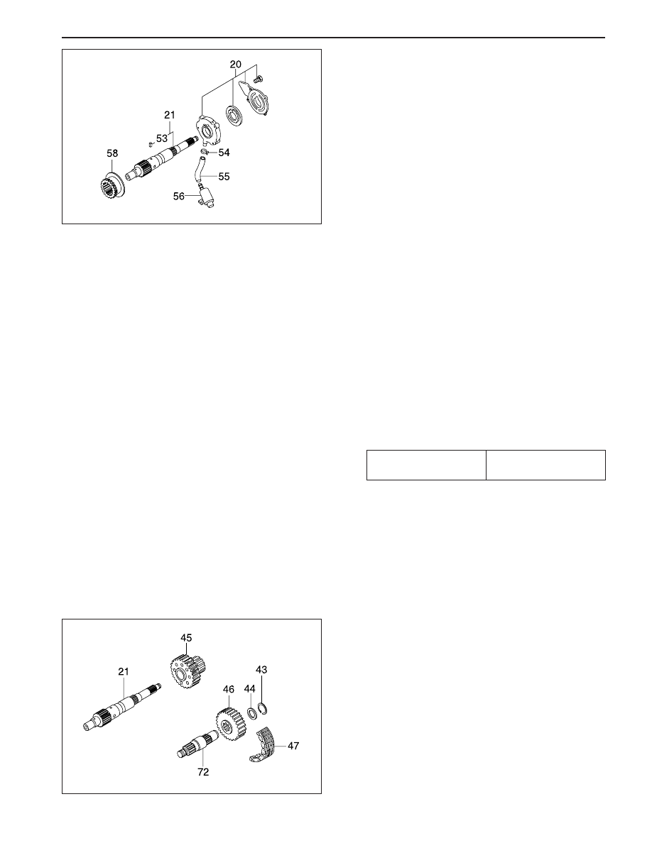
Oil Pump
1. Install the pump front cover to be the “TOP” mark
down and turn the cover to be the “TOP” mark up
when installed in vehicle.
2. Install the 2 pump pins and spring to the output
shaft.
Notice: Flat surface of the pins must point out
and align the center line of pins and spring.
3. Connect the hose coupling to the strainer coupling
and install the strainer foot into the transfer case
slot.
Notice: The hose coupling must face the pump
assembly.
4. Install the pump housing to be the ‘REAR’ mark
up and seat the 2 pump pins inside of the pump
housing by moving pump pins inward and
compressing the spring.
5. Tighten the hose to pump housing by hose clamp.
6. Position the pump rear cover to be the TOP REAR
mark up and located at the top of transfer case
when installed in vehicle. Position the pump
retainer on the cover so that tab on the retainer is
in notch in the transfer case. Apply Loctite to the
bolts and tighten the bolts with turning the output
shaft by hand to make the pump pins move freely.
Installation Notice
Tightening Torque
4 - 8.5 N•m
(35 - 75.5 lb-in)
Drive Chain
1. Position the drive sprocket to the rear output shaft
end and driven sprocket to the front output shaft
end.
2. Install the drive chain onto the sprocket.
3. Holding each sprocket to be the drive chain tight
and parallel with transfer case, install the drive
chain assembly to the output shafts.
4. Rotate the driven sprocket slightly to engage
splines on the front output shaft.
5. Install the spacer to the front output shaft and insert
the snap ring into the shaft groove over spacer.
SSANGYONG MY2002
5D2-40 TRANSFER CASE (PART TIME - 4408)
KAA5D880
KAA5D890
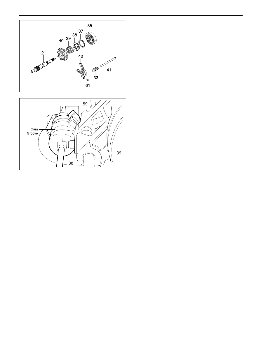
Lockup Shift
1. Install the lockup hub and return spring to the
lockup collar and insert the snap ring.
2. Install the rail shaft through reduction shift fork
assembly previously installed and into the blind
hole in case.
3. Engage the lockup fork into the 2WD/4WD groove
and check operation.
4. Install the shift collar hub to the output shaft spline.
5. Install the previously assembled electric shift cam
and assemble the clutch housing as follows.
•
Rotate the shift cam assembly to right so that
the end of the torsion spring contacts with
reduction shift fork side.
•
Holding the rail shaft, lift up the fork assembly
slightly.
Adjust electric shift cam assembly so that the
roller on reduction shift fork assembly is in
groove in shift cam and button on lockup fork
is on cam end.
•
Install the clutch housing over shift collar hub
and insert the retaining ring into the clutch collar
hub groove.

TRANSFER CASE (PART TIME - 4408) 5D2-41
SSANGYONG MY2002
KAA5D900
Tightening Torque
8 - 11 N•m
(71 - 97 lb-in)
Cover
1. Position the cover to be the open end up on the
work table.
2. P o s i t i o n t h e e n d o f n e e d l e b e a r i n g t o b e
identification mark up and press into the cover
until upper end of bearing is 40.47 - 40.97 mm
below cover face that contacts with transfer case.
3. Press the ball bearing into the cover and install
the snap ring .
4. Install remaining parts as follows.
•
Install the 4 O-rings on the stud bolts of the
clutch coil assembly.
•
Install the clutch coil assembly inside the cover
and tighten 3 nuts.
Installation Notice
•
Install the bearing and motor bearing into the
cover.
KAA5D910
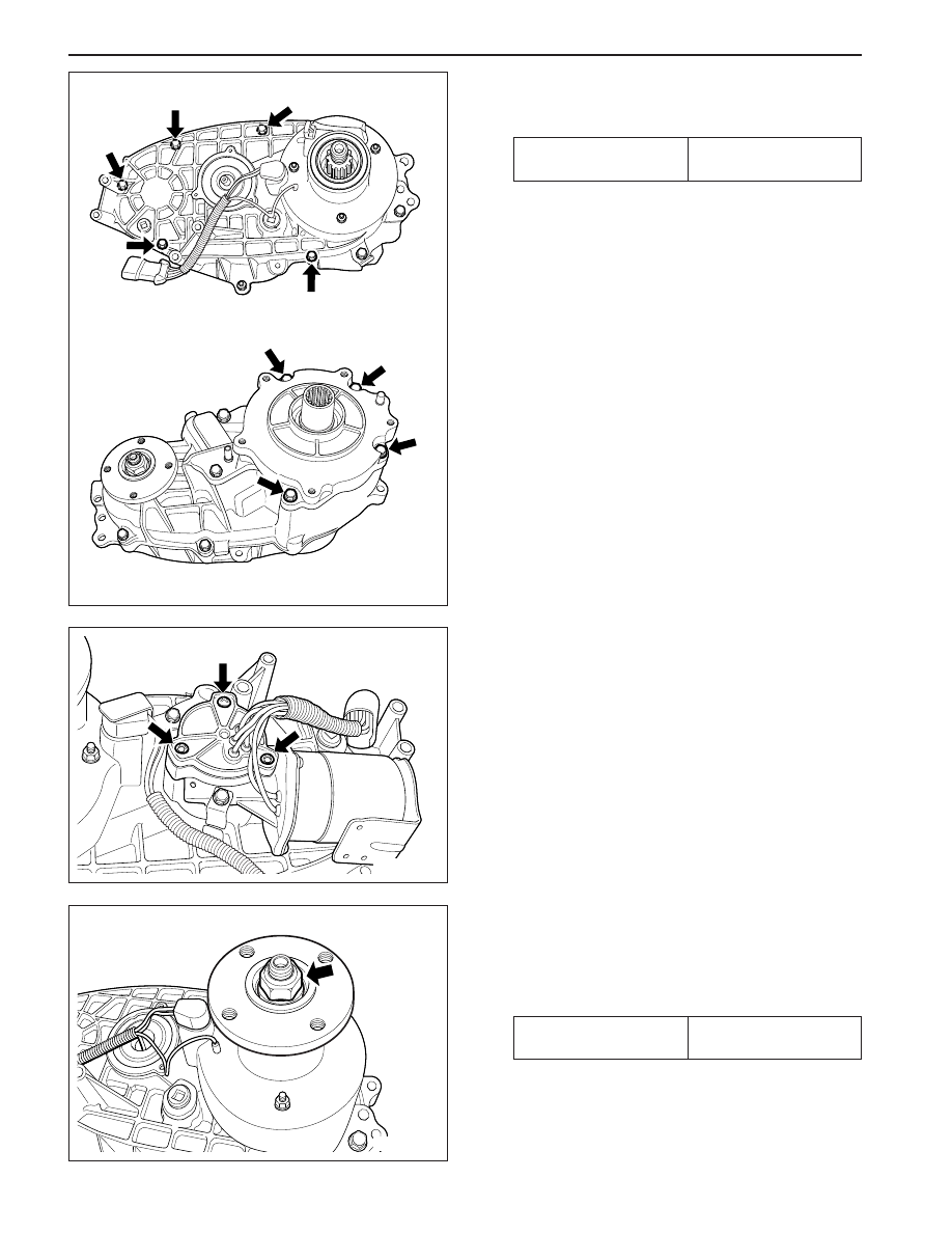
Cover Assembly
1. Install the return spring over rail shaft in the transfer
case.
2. Insert the magnet into the transfer case slot.
3. Apply 1.6 mm bead of Loctite RTV 598 to the
transfer case mounting surface.
Notice: For installation of cover, align the transfer
case with cover not to use excessive force.
4. Install the cover onto the transfer case as follows:
•
Align the cover bores with transfer case pins.
•
Align the cover bearings with output shafts.
•
Align the cover blind hole with rail shaft and
make sure that return spring is not cocked.
SSANGYONG MY2002
5D2-42 TRANSFER CASE (PART TIME - 4408)
5. Tighten 9 bolts positioning identification tag and
wiring clip.
Installation Notice
6. Install the speed gear over output shaft spline in
the cover assembly.
7. Press the new oil seal into the cover assembly.
Tightening Torque
28 - 40 N•m
(21 - 30 lb-ft)
KAA5D920
KAA5D930
KAA5D940
External Electric Shift
1. Align the motor with shift shaft and position the
motor assembly onto the cover.
2. Install the motor to the shift shaft and contact
cover and rotate the motor clockwise direction to
check correct engagement.
3. Insert the O-ring on the speed sensor assembly
to the cover.
4. Install the bracket to the motor assembly and
tighten 3 bolts.
Installation Notice
Tightening Torque
8 - 11 N•m
(71 - 97 lb-in)
Нет комментариевНе стесняйтесь поделиться с нами вашим ценным мнением.
Текст