SsangYong Musso. Manual — part 212
1F-432 ENGINE CONTROLS
SSANGYONG Y158
KAA1C010
KAA1D240
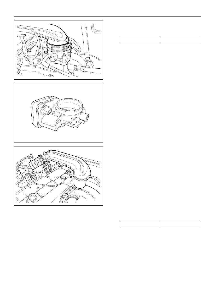
6. Disconnect the throttle body electrical connector.
7. Remove the throttle body bolts.
Installation Notice
8. Remove the vacuum hose.
9. Remove the throttle body and discard the gasket.
Important: Use care in cleaning old gasket material. Sharp
tools may damage sealing surfaces.
10. Installation should follow the removal procedure in
the reverse order.
THROTTLE BODY (INTEGRATED
WITH THE ACTUATOR)
(3.2L DOHC)
Removal and Installation Procedure
1. Disconnect the negative batterry cable.
2. Disconnect the Hot Film Air Mass (HFM) sensor
connector.
3. Disconnect the HFM sensor from the air filter
housing.
Tightening Torque
12 N•m (106 lb-in)
YAA1F790
KAA1D240
KAA1C010
4. Remove the intake air duct mounting bolts.
Installation Notice
5. Remove the intake air duck clamps.
6. Remove the intake air duck.
Tightening Torque
9 N•m (80 lb-in)
ENGINE CONTROLS 1F-433
SSANGYONG Y158
KAC1F260
KAA1D240
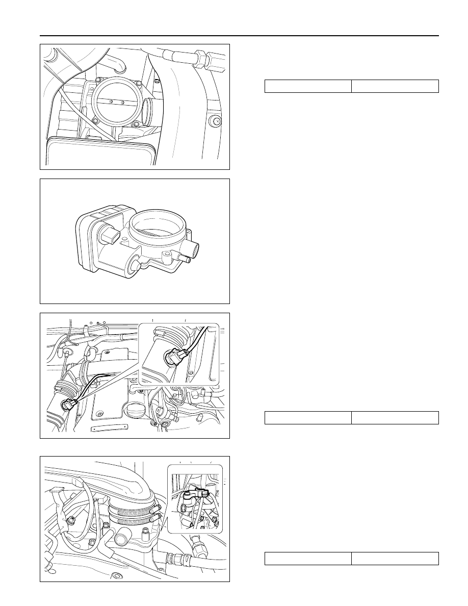
7. Disconnect the throttle body electrical connector.
8. Remove the throttle body bolts.
Installation Notice
9. Remove the vacuum hose.
10. Remove the throttle body and discard the gasket.
Important: Use care in cleaning old gasket material. Sharp
tools may damage sealing surfaces.
11. Installation should follow the removal procedure in
the reverse order.
INTAKE AIR TEMPERATURE
SENSOR (2.3L DOHC)
Removal and Installation Procedure
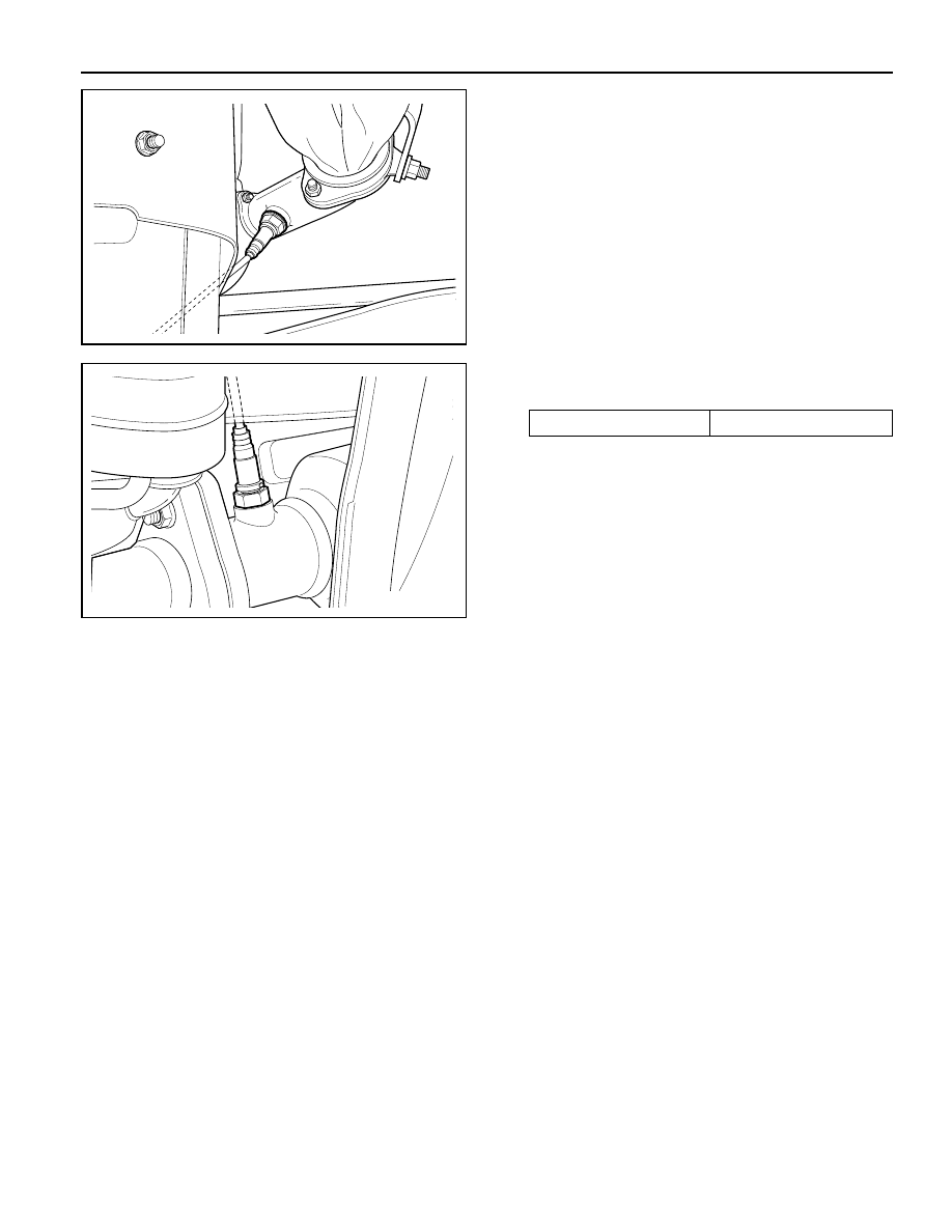
1. Disconnect the negative battery cable.
2. Disconnect the Intake Air Temperature (IAT) sensor
connector.
3. Remove the IAT sensor.
Installation Notice
Tightening Torque
12 N•m (106 lb-in)
KAA1D240
KAC1F260
4. Installation should follow the removal procedure in
the reverse order.
Tightening Torque
22 N•m (16 lb-ft)
MANIFOLD ABSOLUTE PRESSURE
SENSOR (2.3L DOHC)
Removal and Installation Procedure
1. Disconnect the negative battery cable.
2. Disconnect the Manifold Absolute Pressure (MAP)
sensor connector.
3. Remove the MAP sensor retaining bolt.
Installation Notice
4. Installation should follow the removal procedure in
the reverse order.
Tightening Torque
8 N•m (71 lb-in)
KAA1D230
KAC1F270

1F-434 ENGINE CONTROLS
SSANGYONG Y158
KAA1F180
KAA1F190
4. Remove the knock sensor.
5. Installation should follow the removal procedure in
the reverse order.
HOT FILM AIR MASS SENSOR
(3.2L DOHC)
Removal and Installation Procedure
1. Disconnect the negative battery cable.
2. Disconnect the Hot Film Air Mass (HFM) sensor
electrical connector.
3. Remove the HFM sensor retaining screws.
4. Turn the HFM sensor coupling in the direction shown
in the figure in the left so that it gets separated from
the contact surface.
Notice: Make sure the HFM sensor coupling connects
completely with the contact surface installation.
5. Remove the HFM sensor.
6. Installation should follow the removal procedure in
the reverse order.
KONCK SENSOR
Removal and installation Procedure
1. Disconnect the negative battery cable.
2. Disconnect the knock sensor electrical connector
from the intake manifold bracket.
3. Remove the knock sensor mounting bolt from the
knock sensor installed on the cylinder bolck.
Installation Notice
Tightening Torque
25 N•m (18 lb-ft)
KAA1F190
KAA1F180
ENGINE CONTROLS 1F-435
SSANGYONG Y158
KAC1F290
KAC1F280
OXYGEN SENSOR (2.3L DOHC)
Removal and Installation Procedure
1. Disconnect the negative battery cable.
Notice: The Oxygen (O2) sensor uses a permanently
attached pigtail and connector. This pigtail should not be
removed from the O2 sensor. Damage or removal of the
pigtail or the connector could affect proper operation of the
O2 sensor. Do not drop the O2 sensor.
2. Disconnect the electrical connector.
KAC1F280
Important: a special anti-seize compound is used on the
O2 sensor threads. This compound consists consists of a
liquid graphite and glass beads. The graphite will burn
away, but the glass beads will remain, making the sensor
easier to remove. New or serviced sensors will already
have the compound applied to the threads. If a sensor is
removed from any engine and is to be reinstalled, the
threads must have an anti-seize compound applied before
reinstallation.
4. Coat the threads of the O2 sensor with an anti-seize
compound, if needed.
5. Installation should follow the removal procedure in
the reverse order.
3. Carefully remove the O2 from the exhaust pipe.
Installation Notice
Tightening Torque
55 N•m (41 lb-ft)
KAC1F290
Нет комментариевНе стесняйтесь поделиться с нами вашим ценным мнением.
Текст