SsangYong Musso. Manual — part 209
1F-420 ENGINE CONTROLS
SSANGYONG Y158
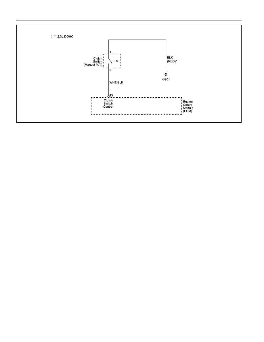
DIAGNOSTIC TROUBLE CODE (DTC) P1813
CLUTCH SWITCH PLAUSIBILITY
Circuit Description
Clutch switch plausibility diagnosis detects whether no
clutch switch signal detects in the corresponding range
(vehicle speed, engine speed) and engine load exceeds
upper load threshold for more than minimum time.
Conditions for Setting the DTC
•••••
DTCs P0101, P0102, P0103, P0335, P0336 and
P0501 are not set.
•••••
Vehicle speed is less than 2.4 km/h.
•••••
Ignition status is on.
•••••
Engine speed is less than 1800 rpm.
•••••
Engine load is greater than 0.6 for more than 5
seconds.
•••••
Start end is reached.
Action Taken When the DTC Sets
•••••
The Malfunction Indicator Lamp (MIL) will illuminate
after two consecutive driving cycles in which the diag-
nostic runs with the fault active.
•••••
The ECM will record operating conditions at the time
the diagnostic fails. This information will be stored in
the Freeze Frame and Failure Records buffers.
•••••
A history DTC is stored.
Conditions for Clearing the MIL/DTC
•••••
The MIL will turn off after three consecutive driving
cycles in which the diagnostic runs without a fault.
•••••
A history DTC will clear after 40 consecutive warm-
up cycles without a fault.
•••••
The DTC(s) can be cleared by using the scan tool.
Diagnostic Aids
An intermittent problem may be caused by a poor con-
nection, rubbed-through wire insulation, or a wire that is
broken inside the insulation.
Any circuitry, should be thoroughly checked for the fol-
lowing conditions:
•••••
Backed-out terminals
•••••
Improper mating
•••••
Broken locks
•••••
Improperly formed
•••••
Damaged terminals
•••••
Poor terminal-to-wire connection
•••••
Physical damage to the wiring harness
Test Description
Number(s) below refer to the step(s) number on the
Diagnostic Table.
1. Euro On-Board Diagnostic (EOBD) System Check
prompts the technician to complete some basic
checks and store the freeze frame and failure
records data on the scan tool if applicable. This
creates an electronic copy of the data taken when
the malfunction occurred. The information is then
stored on the scan tool for later reference.
9. The replacement ECM must be reprogrammed. Re-
fer to the latest Techline procedure for ECM repro-
gramming.
YAB1F240

ENGINE CONTROLS 1F-421
SSANGYONG Y158
1
Step
Action
Value(s)
Yes
No
DTC P1813 Clutch Switch Plausibility
2
3
Perform the Euro On-Board Diagnostic (EOBD) System
Check.
Is the system check complete?
1. Turn the ignition ON, with the engine OFF.
2. Install a scan tool.
3. Press the clutch pedal.
Does the scan tool indicate that the CLUTCH SWITCH
is changed OFF to ON?
1. Turn the ignition OFF.
2. Disconnect the Engine Control Module (ECM)
connector.
3. Turn the ignition ON.
4. Using a Digital Voltmeter (DVM), measure the clutch
switch connector terminal 2 and ECM connector
terminal 43.
Does the resistance near the specifies value?
With a test light connected to battery postive, probe the
clutch switch connector terminal 1.
Does the test light illuminate?
1. Turn the ignition OFF.
2. Replace the clutch switch.
Is the repair complete?
Check the clutch switch connector terminal 1 to ground
for open or short and repair if necessary.
Is the repair complete?
Check for open or short in the wire between clutch
switch connector terminal 2 and ECM connector
terminal 43 and repair if necessary.
Is the repair complete?
1. Turn the ignition OFF.
2. Replace the ECM.
Is the repair complete?
1. If disconnected, reconnect the clutch switch
electrical connector.
2. Using the scan tool, clear the Diagnostic Trouble
Codes (DTCs)
3. Start the engine and idle at normal operating
temperature.
4. Operate the vehicle within the conditions for setting
the DTC as specified in the supporting text.
Does the scan tool indicate that this diagnostic has run
and passed?
Check if any additional DTCs are set.
Are any DTCs displayed that have not been diagnosed?
-
Go to Step 2
Go to “Euro
On-Board
Diagnostic
System Check”
0
Ω
Go to Step 5
Go to Step 8
5
6
-
Go to Step 6
Go to Step 7
7
-
Go to Step 10
-
-
Go to Step 10
-
-
Go to Step 10
-
8
9
10
11
-
Go to Step 11
Go to Step 2
-
Go to Step 10
Go to Step 9
-
Go to
“Diagnostic
Aids”
Go to Step 3
-
Go to
applicable
DTC table
System OK

1F-422 ENGINE CONTROLS
SSANGYONG Y158
KAA1F430
YAA1F710
YAA1F700
ON VEHICLE SERVICE
DISCHARGING THE PRESSURE IN
FUEL SYSTEM (2.3L DOHC)
Removal and Installation Procedure
1. Remove the fuel pressure test connector.
Installation Notice
MAINTENANCE AND REPAIR
DISCHARGING THE PRESSURE IN
FUEL SYSTEM (3.2L DOHC)
Removal and Installation Procedure
1. Remove the fuel pressure test connector.
Installation Notice
2. Remove the fuel pressure in fuel system by pressing
the service valve with a clean, pointy tool.
Notice: Place a cloth so that the fuel doesn't stain around.
3. Installation should follow the removal procedure in
the reverse order.
Tightening Torque
25 N•m (18 lb-ft)
Tightening Torque
25 N•m (18 lb-ft)
YAA1F700
YAA1F710
KAA1F430
ENGINE CONTROLS 1F-423
SSANGYONG Y158
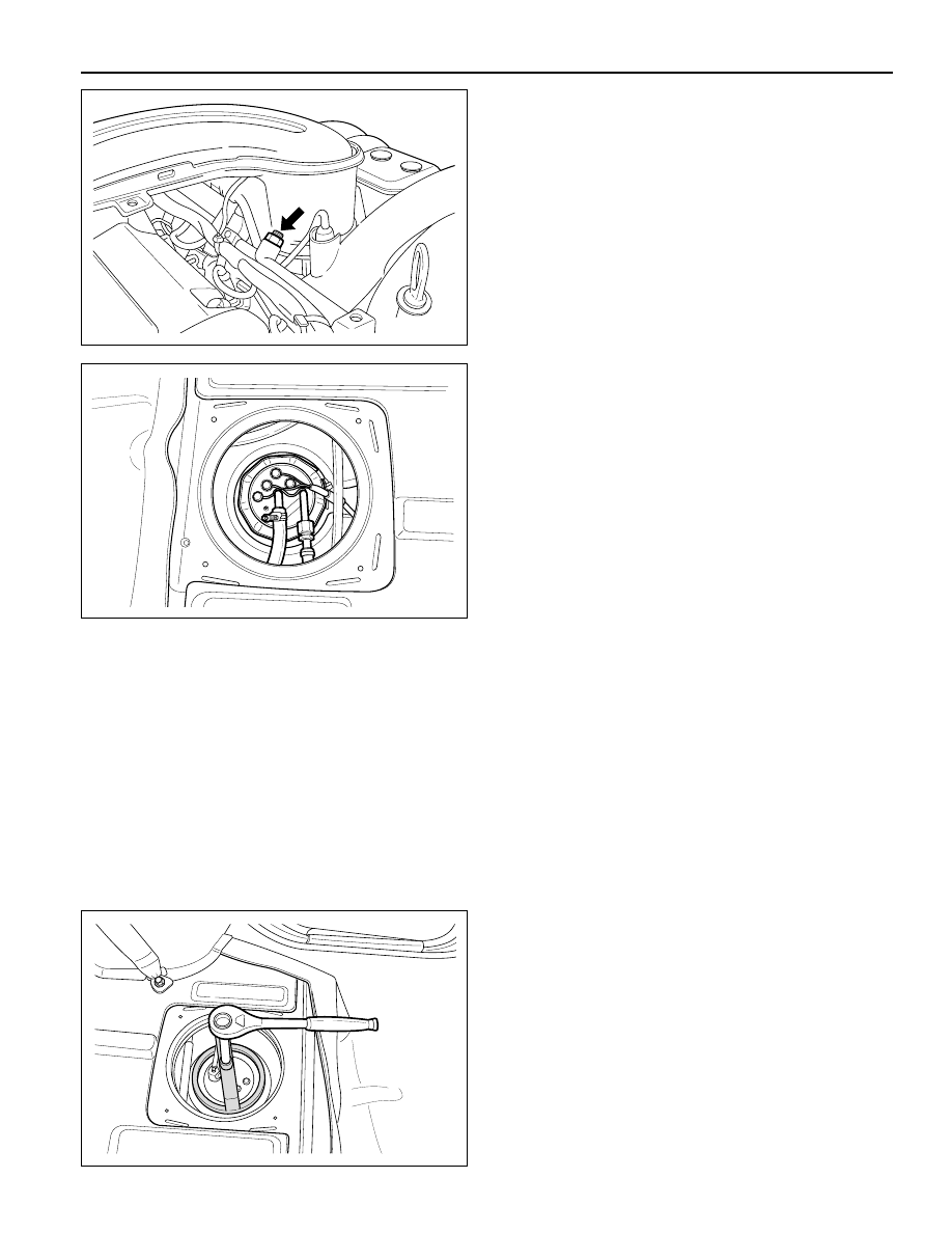
KAA1F440
8. Using the fuel tank cap wrench 661 589 00 46 00,
remove the locking cap.
9. Remove the pump from the fuel tank.
Notice: Check the condition of the seal and replace if
necessary, Drain the fuel before removing the pump.
10. Perform an operational check of the fuel pump.
11. Installation should follow the removal procedure in
the reverse order.
FUEL PUMP
Tool Required
661 589 00 46 00 Fuel Tank Cap Wrench
Removal and Installation Procedure
Caution: The fuel system is under pressure. To avoid
fuel spillage and the risk of personal injury or fire,
it is necessary to relieve the fuel system pressure
before disconnecting the fuel lines.
1. Relieve the fuel system pressure. Refer to "Discharg-
ing the Pressure in Fuel System" in this section.
2. Disconnect the negative battery cable.
3. Put aside the floor carpet to remove the fuel pump
access cover.
4. Remove the fuel pump access cover.
5. Remove the fuel pump wiring connectors.
6. Disconnect the fuel supply and return pipes.
7. Remove the fuel pump locking cap band.
2. Remove the fuel pressure in fuel system by pressing
the service valve with a clean, pointy tool.
Notice: Place a cloth so that the fuel doesn't stain around.
3. Installation should follow the removal procedure in
the reverse order.
KAA1F440
YAA1F170
YAA1F550
Нет комментариевНе стесняйтесь поделиться с нами вашим ценным мнением.
Текст