SsangYong Musso. Manual — part 533
7B/C-12 MANUAL & SEMIAUTO-HVAC
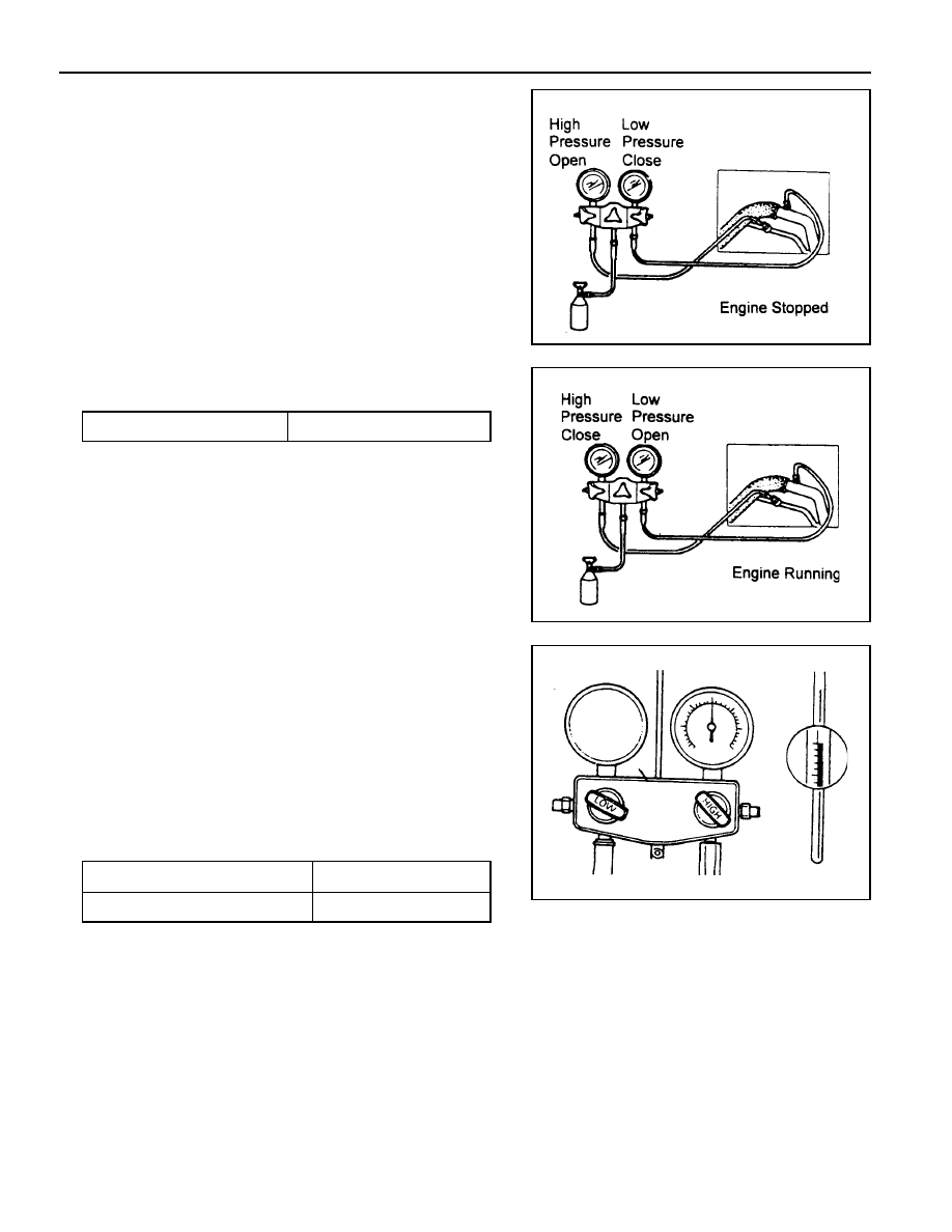
Charging Refrigerant
1. Connect the manifold gauge to the charging valve and
evacuate the system.
2. Connect the center hose of the gauge to the refrigerant
tank.
3. Open the high pressure valve and charge the system with
350g of refrigerant.
4. Close the high pressure valve and start the engine and run
the compressor.
Notice
Never open the high pressure valve when the compressor
is running. Refrigerant gas will be charged reverse.
5. Slowly open the low pressure valve and charge the system
with refrigerant.
Standard
650 - 750 g
6. Close the low pressure valve after charging.
Notice
Checking the pressure through the sight glass is impossible
by applying & R-134a.
7. Stop the engine and disconnect the manifold gauge from
the system.
Operation Check
1. Place a dry bulb thermometer to the front duct.
2. Place a psychrometer close to the inlet of the cooling unit
(under the glove box).
3. Run the engine at 1,500 rpm.
4. Set the blower switch at ‘HI’ and A/C switch ‘ON”.
5. Set the temperature control lever at ‘COOL’.
6. Set the air flow control at ‘REC’.
7. Check that air conditioning system is stabilized.
Temperature of Air Inlet
High Pressure Gauge Reading
25 - 35°C
13.2 - 18.5kg/cm
2
MANUAL & SEMIAUTO-HVAC 7B/C-13
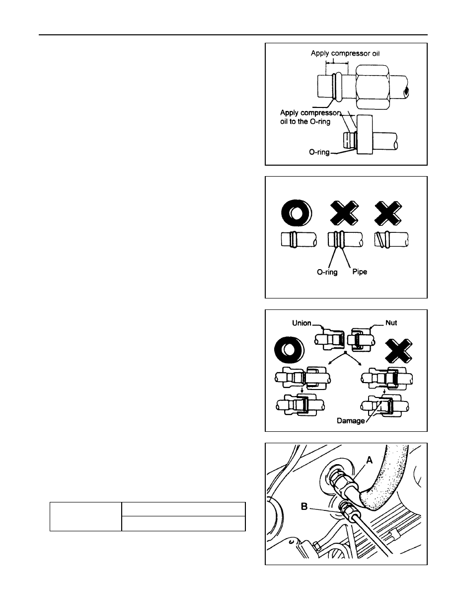
Replacement of Refrigerant Connection (O-ring
Type)
1. When connecting a O-ring type, apply compressor oil to
portions shown in illustration. Be careful not to apply oil to
threaded portion.
Notice
Use specified compressor oil.
2. O-rings must be closely attached to inflated portion of pipe
and always replace used O-rings.
3. After inserting the pipe to the union, tighten the nut by hand
as much as possible and tighten the nut to specified torque.
4. When connecting liquid pipe(B) and low pressure hose(A)
to evaporate pipe, apply compressor oil to the O-ring.
5. When tightening, set the center of pipe and tighten fully.
6. Tighten the nut by specified wrench.
Installation Notice
Tightening Torque
Inlet Side to 12 - 15Nm
Low Pressure Hose (A) 30 - 35 Nm
7B/C-14 MANUAL & SEMIAUTO-HVAC
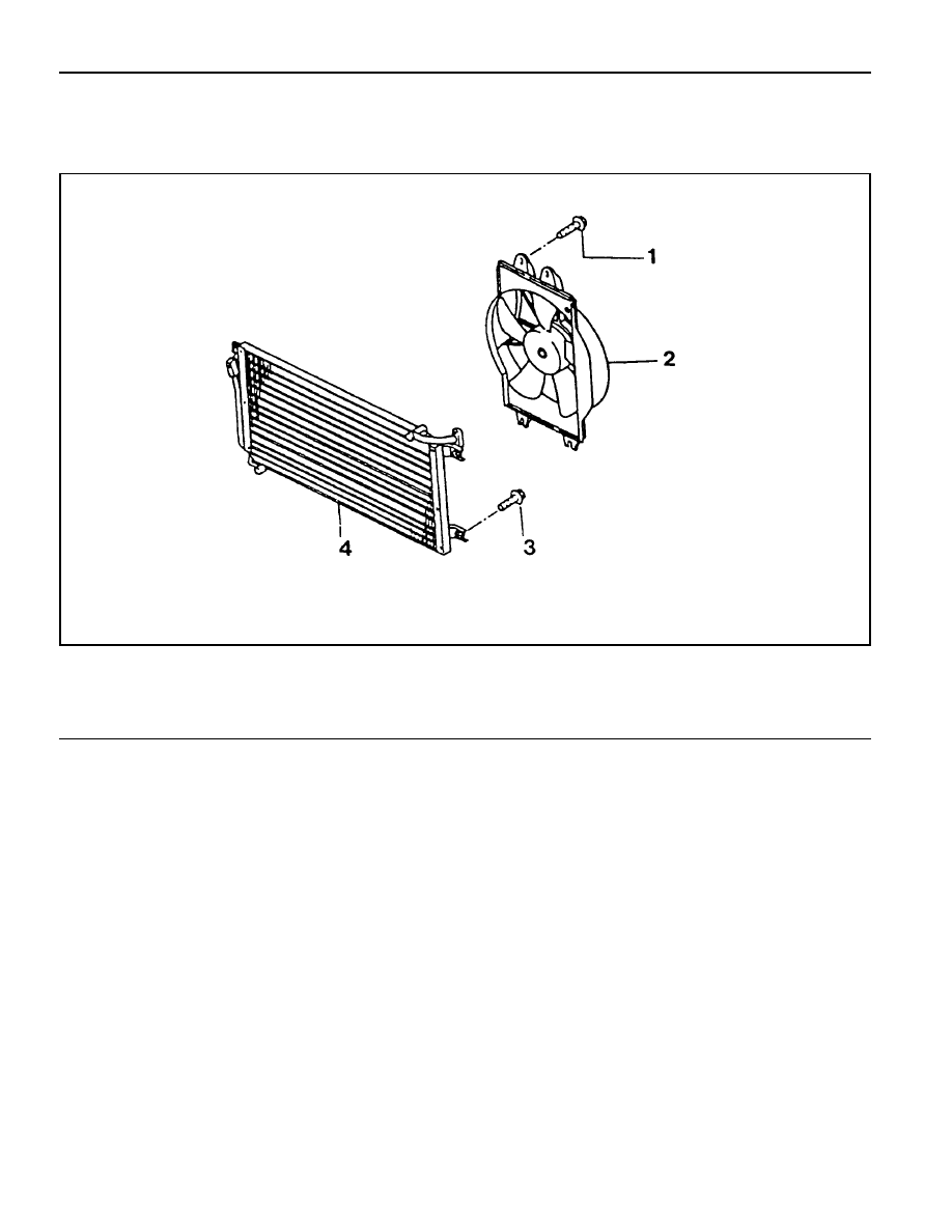
CONDENSER
Preceding Work : Removal of the radiator
1 Bolt
2 Condenser Fan
3 Bolt
4 Condenser
Diesel Engine

MANUAL & SEMIAUTO-HVAC 7B/C-15
Removal & Installation Procedure
1. Disconnect the inlet and outlet pipes of condenser.
Notice
Before disconnection, evacuate the refrigerant from the
system.
2. Remove the mounting bolts (4 EA) and condenser assembly.
3. Installation should follow the removal procedure in the
reverse order.
Нет комментариевНе стесняйтесь поделиться с нами вашим ценным мнением.
Текст