SsangYong Musso. Manual — part 462

AUTOMATIC TRANSMISSION 5A-25
producing a low resistance.
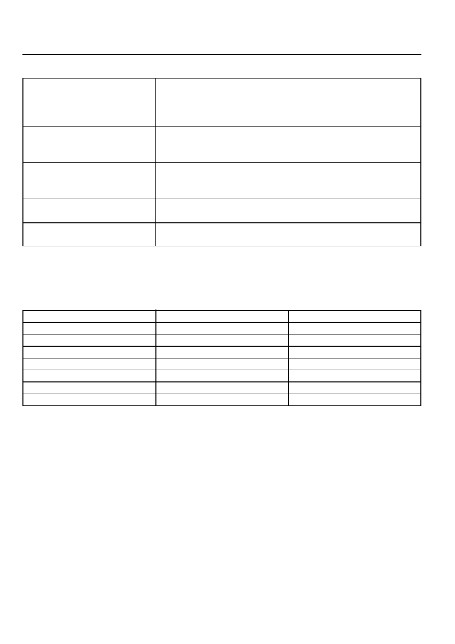
Temperature/Resistance characteristics and location within the solenoid wiring loom are given in tables 3-1 and 3-
2, and figures 3.2 and 3.3.
If the transmission sump temperature exceeds 135°C, the TCU will impose converter lock-up at lower vehicle
speeds and in some vehicles flashes the mode indicator lamp. This results in maximum oil flow through the
external oil cooler and eliminates slippage in the torque converter. Both these actions combine to reduce the oil
temperature in the transmission.
Connects To
Solenoid 1
Solenoid 2
Solenoid 3
Solenoid 4
Solenoid 5
Solenoid 6
Solenoid 7
Solenoid 5
Temp Sensor
Temp Sensor
Wire Color
Red
Blue
Yellow
Orange
Green
Violet
Brown
Green
White
White
Pin No.
1
2
3
4
5
6
7
8
9
10
Table 3.2 - Pin No. Codes for Temperature Sensor Location In Solenoid Loom
Figure 3.3 - Temperature Sensor Location in Solenoid Loom

5A-26 AUTOMATIC TRANSMISSION
I n h i b i t o r
Switch
Throttle Position Sensor
The throttle position sensor(TPS) is a resistance potentiometer
mounted on the throttle body of the engine.
It transmits a signal to the TCU proportional to the throttle plate
opening.
The potentiometer is connected to the TCU by three wires:
5 volts positive supply, earth and variable wiper voltage.
Throttle voltage adjustments are as follows:
!
Closed throttle voltage is 0.2V to 1.0V.
!
Wide open throttle voltage is 3V -4.7V.
These measurements are taken between pins 29 and 27 of
the TCU.
Maintaining good shift feel through the transmission life span
is dependant on having an accurate measure of
the engine throttle position. To achieve this the TCU
continuously monitors the maximum and minimum throttle
potentiometer voltages and, if a change occurs, stores the new
voltage values.
However these limits will be lost and will require relearning
should a new TCU be installed, or the throttle calibration data
is cleared by the execution of a particular sequence, This last
instance depends on the installation, and reference should be
made to the Diagnostics Section of this manual. The relearning
will happen automatically
Notice
Above figure of T.P.S. is for the diesel engine
which is installed on the injection pump.
Gear Position Sensor
The gear position sensor is incorporated in the inhibitor switch
mounted on the side of the transmission case.
(Refer to figure 3.5.) The gear position sensor is a multi-function
switch providing three functions:
!
Inhibit starting of the vehicle when the shift lever is in a
position other than Park or Neutral
!
Illuminate the reversing lamps when Reverse is
selected indicate to the TCU which lever position has
been selected by way of a varying resistance (Refer to
table 3.3.)
Figure 3.5 - Inhibitor Switch

AUTOMATIC TRANSMISSION 5A-27
Shift Lever Position
Manual 1
Manual 2
Manual 3
Drive
Netural
Reverse
Park
Resistance (OHMS)
1k - 1.4k
1.8k - 2.2k
3k - 3.4k
4.5k - 4.9k
6.8k - 7.2k
10.8k - 11.2k
18.6k - 19k
Table 3.3 - Readings for Resistance/Shift Lever Positions
Diagnostics Inputs
The diagnostics control input or K-line is used to initiate the outputting of diagnostics data from the TCU to a diagnostic
test instrument. This input may also be used to clear the stored fault history data from the TCU’s
retentive memory. Connection to the diagnostics input of the TCU is via a connector included in the vehicle’s wiring
harness or computer interface. Refer to the vehicle manufacturer’s manual for the location of the self test
connectors.
Battery Voltage Monitoring Input
The battery voltage monitoring input connects to the positive side of the battery. The signal is taken from the
main supply to the TCU.
If operating conditions are such that the battery voltage at the TCU falls below 11.3V the transmission will adopt a ‘low
voltage’ mode of operating in which shifts into first gear are inhibited. All other shifts are allowed but may not occur
because of the reduced voltage. This condition normally occurs only when the battery is in poor condition.
When system voltage recovers, the TCU will resume normal operation after a 3 second delay period.
TCU Outputs
The outputs from the TCU are supplied to the components described below:
Solenoids
The TCU controls seven solenoids. Solenoids 1 to 6 (S1 to S6) are mounted in the valve body, while Solenoid 7 (S7)
is mounted in the pump cover. The normal state (OPEN/CLOSED) and the functions associated with the solenoids
are detailed in table 3.4. Table 3.5 details the S1 and S2 logic for static gear states. The logic during gear changes for
S1 to S4 and S7 is detailed in table 3.6.
5A-28 AUTOMATIC TRANSMISSION
Table 3.4 - Solenoid States and Functions
Table 3.5 - Solenoid Logic for Static Gear States
Solenoids 1 and 2
Solenoids 3 and 4
Solenoid 5
Solenoid 6
Solenoid 7
S1 and S2 are normally open On/off solenoids that set the selected gear.
These solenoids determine static gear position by operating the shift valves.
Refer to table 3.5. Note that S1 and S2 solenoids also send signal pres-
sure to allow or prohibit rear band engagement.
S3 and S4 are normally open On/off solenoids that combine to control
shift quality and sequencing. S3 switches the clutch regulator valve off or
on. S4 switches the front band regulator valve off or on.
S5 is a variable force solenoid that ramps the pressure during gear
changes. This solenoid provides the signal pressure to the clutch and
band regulator, thereby controlling the shift pressures.
S6 is a normally open On/off solenoid that sets the high/low level of line
pressure, Solenoid off gives high pressure.
S7 is a normally open On/off solenoid that controls the application of the
converter clutch. Solenoid on activates the clutch.
S2
ON
ON
OFF
OFF
OFF
OFF
OFF
S1
ON
OFF
OFF
ON
OFF
OFF
OFF
Gear
1st
2nd
3rd
4th
Reverse
Neutral
Park
Нет комментариевНе стесняйтесь поделиться с нами вашим ценным мнением.
Текст