SsangYong Musso. Manual — part 463
AUTOMATIC TRANSMISSION 5A-29
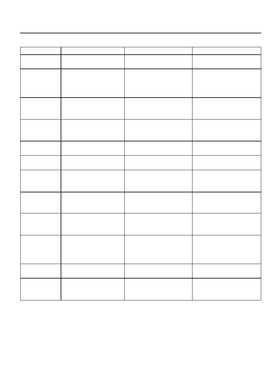
Table 3.6- Solenoid Operation During Gearshifts
To Initiate Shift
S1 OFF
S4 ON
S1 OFF
S2 OFF
S3 ON
S4 ON
S2 OFF
S3 ON
S4 ON
S2 OFF
S3 ON
S4 ON
S1 ON
S4 ON
S4 ON
S3 ON
S3 ON
S4 ON
S2 ON
S4 ON
S3 ON
S4 ON
S4 ON
S7 ON
To Complete Shift
S4 OFF
S3 OFF
S4 OFF
S3 OFF
S4 OFF
S3 OFF
S4 OFF
S4 OFF
S1 OFF
S4 OFF
S1 OFF
S2 ON
S3 OFF
S2 ON
S3 OFF
S4 OFF
S4 OFF
S1 ON
S2 ON
S3 OFF
S4 OFF
S1 ON
S4 OFF
S7 OFF
Typical S5 Current Ramp
750mA to 600mA
850mA to 750mA
850mA to 750mA
700mA to 500mA
750mA to 600mA
750mA to 900mA
750mA to 950mA
600mA to 1000mA
600mA to 450mA @ 20 kph.
550mA to 400mA @ 60 kph.
800mA to 650mA @ 100 kph.
700mA to 950mA
800mA to 950mA
700mA to 400mA
600mA to 100mA
Shift
1-2
1-3
1-4
2-3
3-4
4-3
4-2
4-1
3-2
3-1
2-1
Conv. Clutch
ON
OFF
5A-30 AUTOMATIC TRANSMISSION
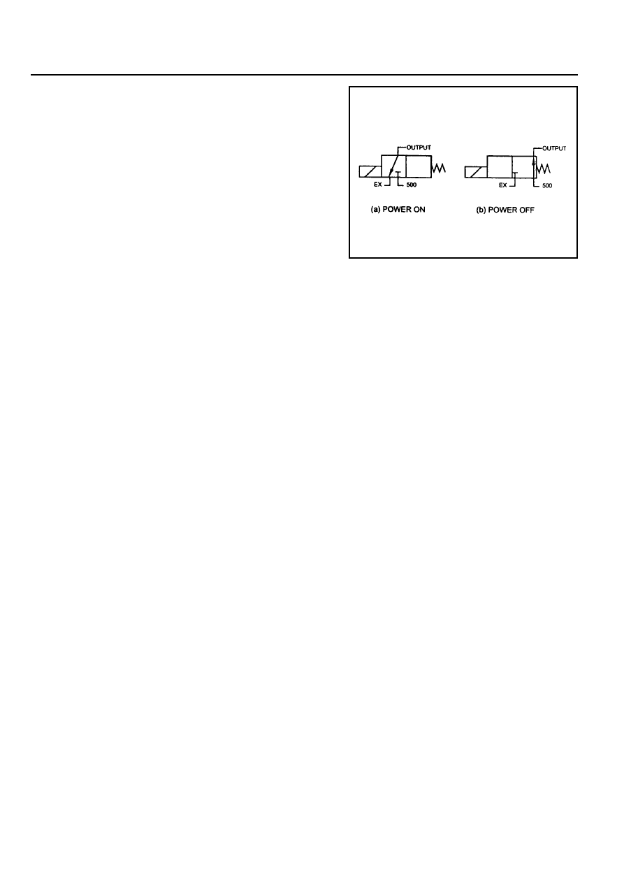
Solenoid Valve Symbols (On/off Solenoids)
The solenoid symbol shown adjacent to each solenoid on the
hydraulic system schematics indicates the state of the oil flow
through the solenoid valve with the power On or 0ff. Refer to
figure 3.6 for the On/off operational details of NO solenoid
valves.
Normally Open (NO) Solenoid
POWER ON
Line 500 port is closed. The output port is open to exhaust at
the solenoid valve.
POWER OFF
The exhaust port is closed. The output port is open to line 500,
Figure 3.6- Normally Open (NO) Symbols
Variable Pressure Solenoid Multiplexing System
Friction element shifting pressures are controlled by the variable pressure solenoid (VPS).
Line pressure is completely independent of shift pressure and is a function of throttle position, gear state and engine
speed.
S5 is a proportional or variable pressure solenoid that provides the signal pressure to the clutch and band regulator
valves thereby controlling shift pressures.
VPS pressure is multiplexed to the clutch regulator valve, the band regulator valve and the converter clutch regulator
valve during automatic gearshifts.
A variable pressure solenoid produces a hydraulic pressure inversely proportional to the current applied. During a
gearshift the TCU applies a progressively increasing or decreasing (ramped) current to the solenoid. Current applied
will vary between a minimum of 200 mA and a maximum of 1000 mA, Increasing current decreases output (55)
pressure. Decreasing current increases output (55) pressure.
Line 500 pressure, (approximately 440 to 560 kPa), is the reference pressure for the VPS, and the VPS output
pressure is always below line 500 pressure.
When the VPS is at standby, that is no gearshift is taking place, the VPS current is set to 200 mA giving maximum
output pressure.
Under steady state conditions the band and clutch regulator valve solenoids are switched off. This applies full Line
500 pressure to the plunger and because Line 500 pressure is always greater than S5 pressure it squeezes the S5
oil out between the regulator valve and the plunger. The friction elements are then fed oil pressure equal to Line 500
multiplied by the amplification ratio.
When a shift is initiated the required On/off solenoid is switched on cutting the supply of Line 500 to the plunger.
At the same time the VPS pressure is reduced to the ramp start value and assumes control of the regulator valve by
pushing the plunger away from the valve. The VPS then carries out the required pressure ramp and the timed shift is
completed by switching Off the On/off solenoid and returning the VPS to the standby pressure.
This system enables either the band or clutch or both to be electrically controlled for each gearshift.
Mode Indicator Light
Depending on the application, the mode indicator light may be used to indicate the mode that has been selected or
if an overheat condition exists. The mode indicator light is usually located on the instrument cluster.
Communication Systems
CAN
The controller area network (CAN) connects various control modules by using a twisted pair of wires, to share
common information. This results in a reduction of sensors and wiring. Typical applications include using the engine
controller to obtain the actual engine speed and throttle position, and adding these to the network. The ABS controller
(if fitted) can be used to obtain the road speed signal. This information is then available to the TCU without any
additional sensors.
AUTOMATIC TRANSMISSION 5A-31
K-Line
The K-line is typically used for obtaining diagnostic information from the TCU. A computer with a special interface is
connected to the TCU and all current faults, stored faults, runtime parameters are then available. The stored fault
codes can also be cleared.
The K-line can be used for vehicle coding at the manufacturer’s plant or in the workshop. This allows for one TCU
design to be used over different vehicle models. The particular code is sent to the microprocessor via the K line and
this results in the software selecting the correct shift and VPS ramp parameters.
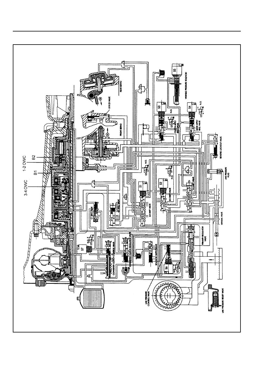
HYDRAULIC CONTROL SYSTEM
The hydraulic controls are located in the valve body, pump body and main case.
The valve body contains the following:
!
Manual valve,
!
Three shift valves,
!
Sequence valve,
!
solenoid supply pressure regulator valve,
!
line pressure control valve,
!
clutch apply regulator valve,
!
band apply regulator valve,
!
S1 to S6, and
!
Reverse lockout valve.
!
The pump body contains the following:
!
Primary regulator valve for line pressure,
!
converter clutch regulator valve,
!
converter clutch control valve,
!
S7,and
!
C1 bias valve.
The main case contains the following:
!
B1R exhaust valve
The hydraulic control system schematic is shown at figure 3.7.
All upshifts are accomplished by simultaneously switching on a shift valve(s), switching VPS pressure to the band
and/or clutch regulator valve, and then sending the VPS a ramped current. The shift is completed by switching the
regulators off and at the same time causing the VPS to reach maximum . pressure. All downshifts are accomplished
by switching VPS pressure to the band and/or clutch regulator valve and sending a ramped current to the VPS. The
shift is completed by simultaneously switching the regulators off, switching the shift valves and at the same time
causing the VPS to return to stand-by pressure.
The primary regulator valve is located in the pump cover and supplies four line pressures; high and low for forward
gears, and high and low for reverse. This pressure has no effect on shift quality and merely provides static clutch
capacity during steady state operation. Low pressure can be obtained by activating an On/off solenoid with high line
pressure being the default mode.
Torque converter lock-up is initiated by toggling the converter clutch control valve with an On/off solenoid. The actual
apply and release of the clutch is regulated by the VPS via the converter clutch regulator valve. As an additional
safety feature, the lock-up is hydraulically disabled in first and second gear by the bias valve which only supplies oil
to the lock-up solenoid when C1 is applied in third and fourth gears. This prevents the vehicle from being rendered
immobile in the unlikely event of S7 becoming stuck.
The solenoid supply valve provides reference pressure for all the solenoids.
5A-32 AUTOMATIC TRANSMISSION
Figure 3.7 - Hydraulic Control Circuit
Нет комментариевНе стесняйтесь поделиться с нами вашим ценным мнением.
Текст