SsangYong Musso. Manual — part 511
5D1-28 TRANSFER CASE (PART TIME 4408)
6. Install the planet carrier assembly onto the input shaft
and install the thrust washer. Press the bearing over
input shaft.
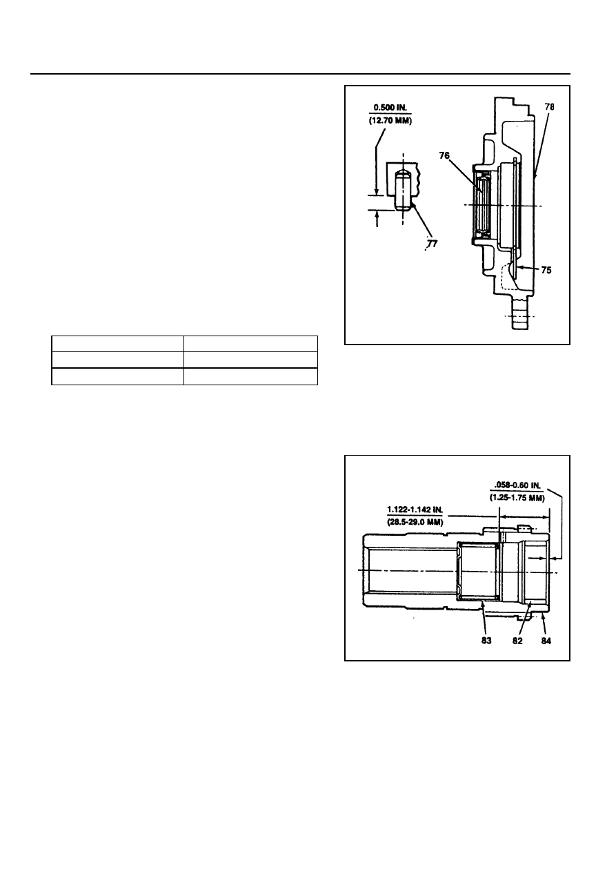
7. After pressing the bearing, install the retaining ring.
8. Press the pin into the front adapter.
9. Slowly press the oil seal into the front adapter.
10. Install the front adapter assembly.
Notice
After installation, make sure that snap ring is correctly
installed into the groove.
11. Position the input shaft assembly over front cover and
engage into the bearing groove by expanding the ends of
snap ring.
12. Apply 1.6mm bead of sealant on the mounting face for
the transfer case and tighten the 6 bolts.
13. Install the breather.
75
Snap Ring
76
Oil Seal
77
Spiral Pin
78
Front Adapter
82
Sleeve Bearing
83
Needle Bearing
84
Input Shaft
Item
6 Bolts
Breather
Tightening Torque
28 - 48 Nm
8 - 20 Nm

TRANSFER CASE (PART TIME 4408) 5D1-29
Front Output Shaft
1. Position the output shaft in transfer case and install the
companion flange assembly, oil seal, washer and nut.
2. Holding the companion flange, tighten the nut.
65 Nut
66 Washer
67 Oil Seal
70 Companion Flange
71 Output Shaft (Front)
111 Case
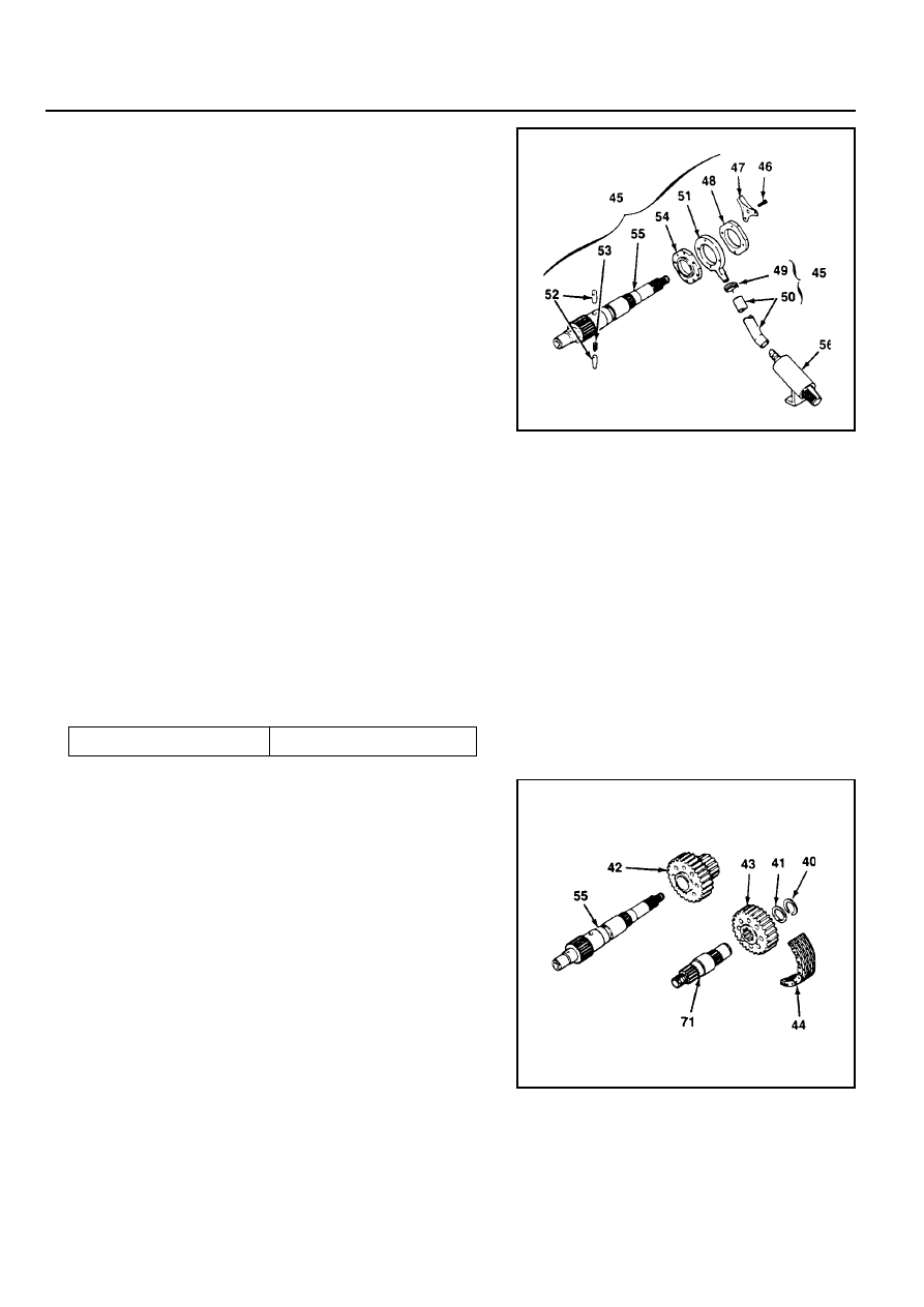
55
Output Shaft
57
Reduction Hub
58
Shift Fork Facing
59
Reduction Shift Fork Assembly
60
Roller, Pin and Retainer Assembly
61
Retainer
62
Pin
63
Roller Cam
64
Reduction Shift Fork
Reduction Shift Parts
1. Install the new pin, roller and retainer into the reduction
shift fork.
2. Press the pin, roller and retainer into the reduction spilt fork
bore completely.
Notice
Make sure that the cam roller turns freely.
3. Install the 2 fork facing on the reduction shift fork assembly.
4. Install the reduction shift fork onto the previously installed
reduction hub in the transfer case.
5. Install the output shaft spline into the reduction hub and
engage the output shaft end with input shaft bearing.
Notice
For installation of the output shaft, assemble
the oil pump temporarily.
5D1-30 TRANSFER CASE (PART TIME 4408)
Oil Pump
1. Install the pump front cover to be the ‘TOP’ mark down and
turn the cover to be the ‘TOP’ mark up when installed in
vehicle.
2. Install the 2 pump pins and spring to the output shaft.
Notice
Flat surface of the pins must point out and align the center
line of pins and spring.
3. Connect the hose coupling to the strainer coupling and
install the strainer foot into the transfer case slot.
Notice
The hose coupling must face the pump assembly.
4. Install the pump housing to be the 'REAR' mark up and seat
the 2 pump pins inside of the pump housing by moving
pump pins inward and compressing the spring.
5. Tighten the hose to pump housing by hose clamp.
6. Position the pump rear cover to be the ‘TOP REAR’ mark
up and located at the top of transfer case when installed in
vehicle. Position the pump retainer on the cover so that tab
on the retainer is in notch in the transfer case. Apply Loctite
to the bolts and tighten the bolts with turning the output
shaft by hand to make the pump pins move freely.
45
Shaft and Pump Assembly
46
Bolt
47
Pump Retainer
48
Rear Pump Cover
49
Hose Clamp
50
Hose Coupling
54
Pump Housing
52
Pump Pin
53
Spring
54
Front Pump Cover
55
Output Shaft
56
Strainer
40
Snap Ring
41
Spacer
42
Drive Sprocket
43
Driven Sprocket
44
Drive Chain
55
Output Shaft (Rear)
71
Output Shaft (Front)
Drive Chain
1. Position the drive sprocket to the rear output shaft end and
driven sprocket to the front output shaft end.
2. Install the drive chain onto the sprocket.
3. Holding each sprocket to be the drive chain tight and parallel
with transfer case, install the drive chain assembly to the
output shafts.
4. Rotate the driven sprocket slightly to engage splines on
the front output shaft.
5. Install the spacer to the front output shaft and insert the
snap ring into the shaft groove over spacer.
Tightening Torque
4 - 8.5 Nm
TRANSFER CASE (PART TIME 4408) 5D1-31
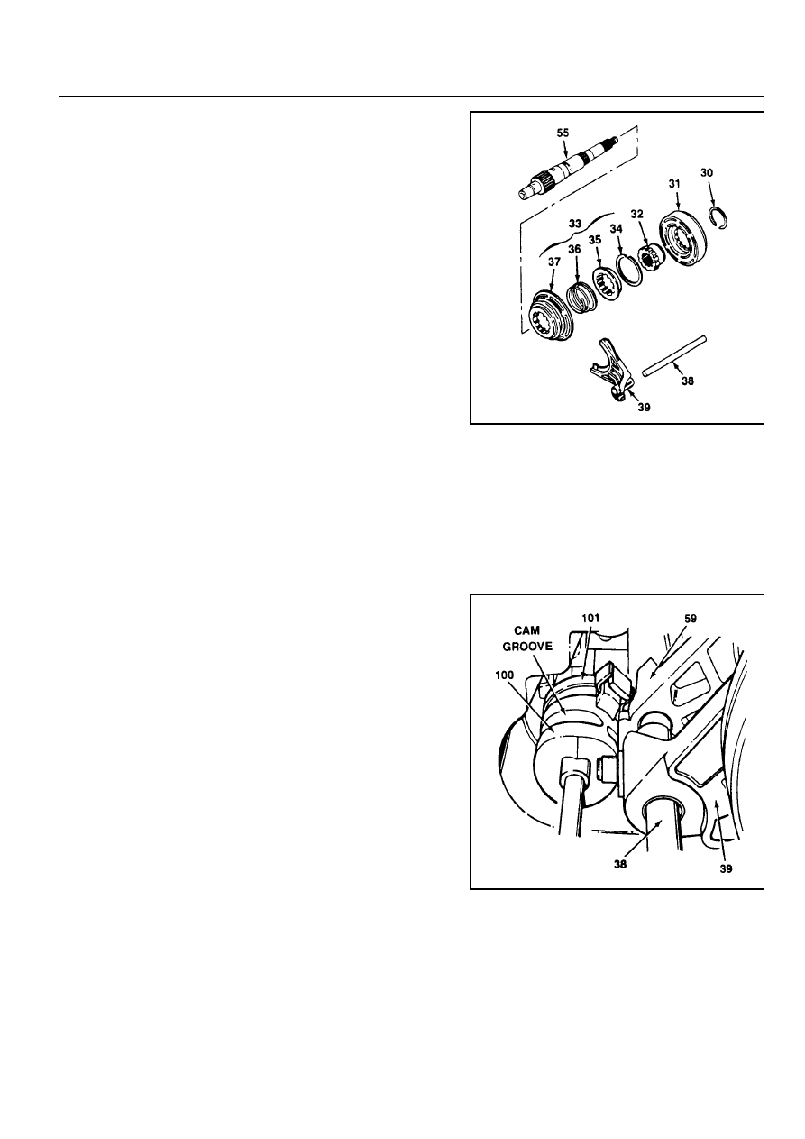
Lockup Shift
1. Install the lockup hub and return spring to the lockup collar
and insert the snap ring.
2. Install the rail shaft through reduction shift fork assembly
previously installed and into the blind hole in case.
3. Engage the lockup fork into the 2WD/4WD groove and
check operation.
4. Install the shift collar hub to the output shaft spline.
5. Install the previously assembled electric shift cam and
assemble the clutch housing as follows.
!
Rotate the shift cam assembly to right so that the end of
the torsion spring contacts with reduction shift fork side.
!
Holding the rail shaft, lift up the fork assembly slightly.
Adjust electric shift cam assembly so that the roller on
reduction shift fork assembly is in groove in shift cam
and button on lockup fork is on cam end.
!
Install the clutch housing over shift collar hub and insert
the retaining ring into the clutch collar hub groove.
30
Retaining Ring
31
Clutch Housing
32
Shift Collar Housing
33
2WD/4WD
Lockup Assembly
34
Snap Ring
38
Rail Shaft
39
Lockup Fork
59
Reduction Shift Fork Assembly
100
Electric Shift Cam
101
Torsion Spring
35
Lockup Hub
36
Return Spring
37
Lockup Collar
38
Rail Shaft
39
Lockup Fork
55
Output Shaft
Нет комментариевНе стесняйтесь поделиться с нами вашим ценным мнением.
Текст