SsangYong Musso. Manual — part 247
M162 ENGINE MECHANICAL 1B1-31
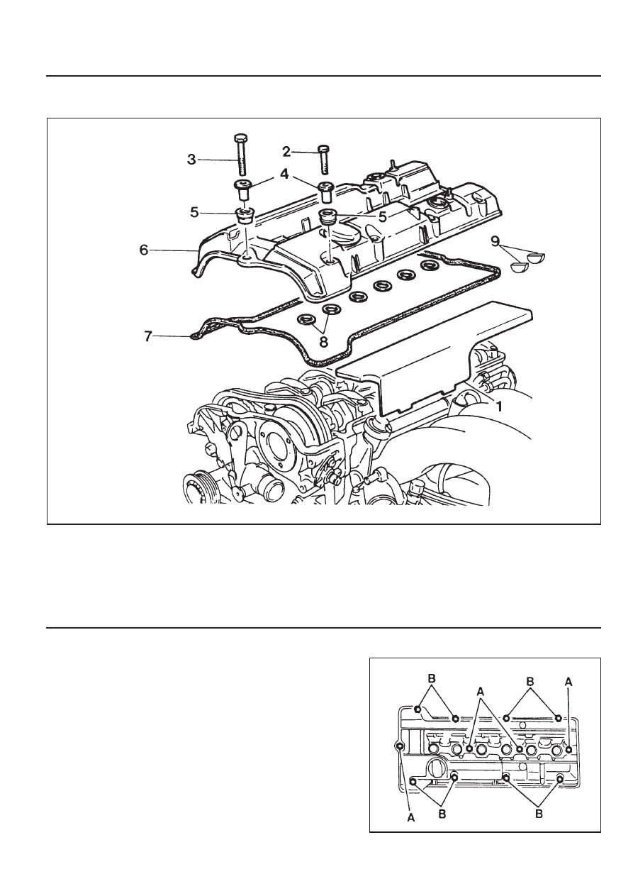
CYLINDER HEAD COVER
1 Ignition Cable Dust Cover
2 Bolt (M6 x 65, 8 pieces) . . . . . . . 9-11 Nm
3 Bolt (M6 x 50, 4 pieces) . . . . . . . 9-11 Nm
4 Spacer Sleeve
5 Thrust Piece
Composition of The Cylinder Head Cover Bolts
A. M6 x 50, 4 Pieces - Bolts + Washers
B. M6 x 65, 8 Pieces - Bolts + Washers
6 Cylinder Head Cover
7 Gasket . . . . . . . . . . . . ... Replace
8 Spart Plug Hole Seal . . . . . . . .. Replace
9 Camshaft Seal . . . . . . . . . ... Replace
1B1-32 M162 ENGINE MECHANICAL
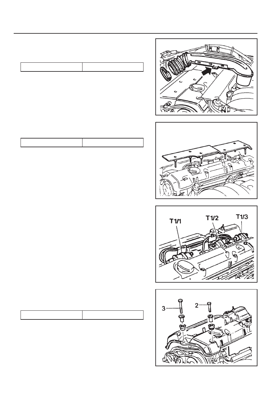
Removal & Installation Procedure
1. Remove the intake air duct.
Installation Notice
2. Remove the ignition cable cover.
Installation Notice
3. Remove the spark plug connector and ignition cable.
4. Unscrew all the bolts (2,3) and remove the head cover and
the gasket.
Installation Notice
Notice
Unscrew the seven (M6 x 60) bolts and remove the ignition
cable cover.
Notice
Replace the gasket with a new one if necessary.
5. Installation should follow the removal procedure in the
reverse order.
6. Check for oil leaks by operating the engine.
Tightening Torque
8 - 9 Nm
Tightening Torque
9 - 10 Nm
Tightening Torque
9 - 10 Nm
M162 ENGINE MECHANICAL 1B1-33
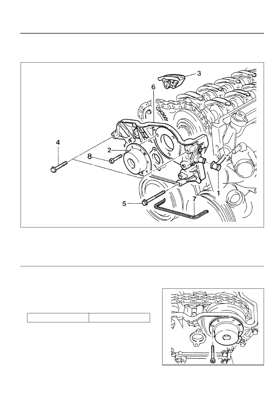
CYLINDER HEAD FRONT COVER
Preceding Work : Removal of cylinder head cover
Removal of coolant connection fitting
1 Camshaft Position Sensor
2 Magnet Assembly
3 Upper Guide Rail
4 Bolt (M6 x 60, 3 pieces) . . . . . 22.5-27.5 Nm
5 Bolt (M8 x 80, 3 pieces) . . . . . 22.5-27.5 Nm
6 Front Cover
7 Rubber Gasket . . . . . . . . . .. Replace
8 Bolt (M6 x 16, 3 pieces) . . . . . . . 9-11 Nm
Removal & Installation Procedure
1. Remove the magnet assembly.
Installation Notice
Tightening Torque
9 - 11 Nm
1B1-34 M162 ENGINE MECHANICAL
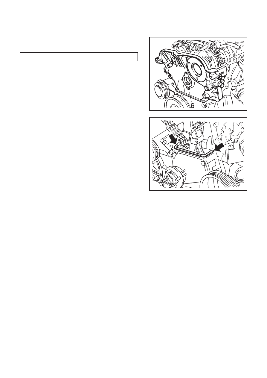
2. Remove the cylinder head front cover (6).
Installation Notice
4. Remove the gasket (arrow).
Installation Notice
Replace the gasket with new one and apply the sealant.
5. Installation should follow the removal procedure in the
reverse order.
Apply the sealant at the mating surface of the cylinder head
and the front cover.
3. Remove the upper guide rail pin and the guide rail (3).
Installation Notice
Install it while the chain tensioner is loose.
Tightening Torque
22.5 - 27.5 Nm
Нет комментариевНе стесняйтесь поделиться с нами вашим ценным мнением.
Текст