SsangYong Musso. Manual — part 248
M162 ENGINE MECHANICAL 1B1-35
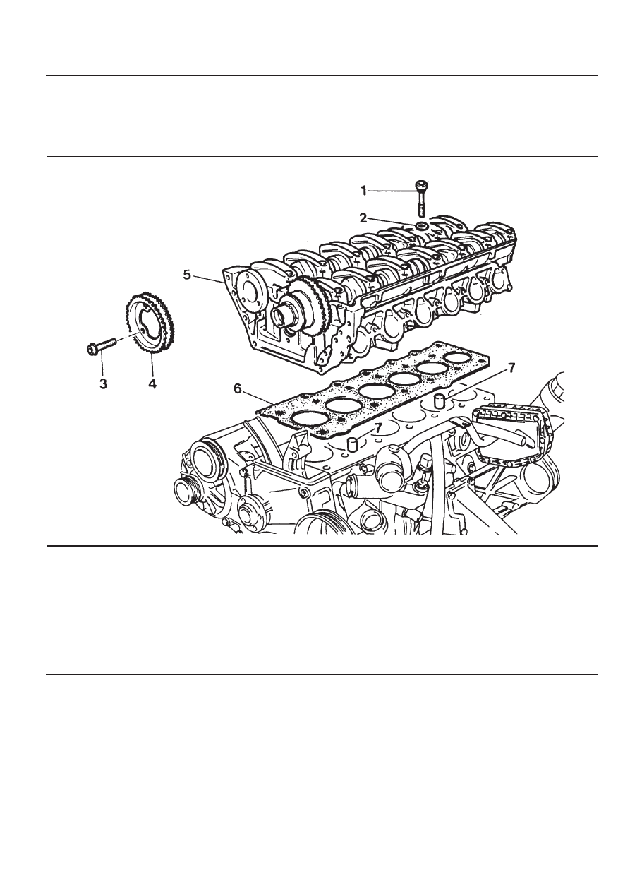
CYLINDER HEAD
Preceding Work : Removal of cylinder head cover
Removal of cylinder head front cover
Removal of upper intake manifold
1 Cylinder Head Bolt (14 pieces)
. . . . . . . . . . . . . 1st step 55 Nm
2nd step 90°
3rd step 90°
2 Washers (14 pieces)
3 Flange Bolts (3 pieces) . . . . 1st step 20 Nm
2nd step 90°
4 Exhaust Camshaft Sprocket
5 Cylinder Head
6 Gasket . . . . . . . . . . . . ... Replace
7 Dowel Sleeve
1B1-36 M162 ENGINE MECHANICAL
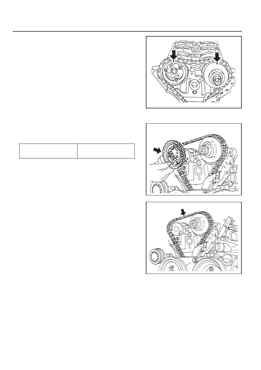
4. Remove the three flange bolts in the exhaust camshaft
sprocket.
Installation Notice
5. Separate the chain from the camshaft sprockrt.
Notice
Be careful not to drop the chain into the timing case.
Do not reuse the removed bolts.
Tools Required
000 589 01 10 00 Box Wrench Insert
116 589 02 34 00 Screw-fixed Pin
116 589 20 33 00 Sliding Hammer
Removal & Installation Procedure
1. Rotate the crankshaft so that the piston of number 1 cylinder
is at TDC.
Notice
Rotate the crankshaft in the normal engine direction.
2. Put the alignment marks (arrows) on the timing chain and
camshaft sprocket.
3. Drain the coolant from the crankcase.
Tightening Torque
1st step 18 - 22 Nm
2nd step 90° ± 5°
M162 ENGINE MECHANICAL 1B1-37
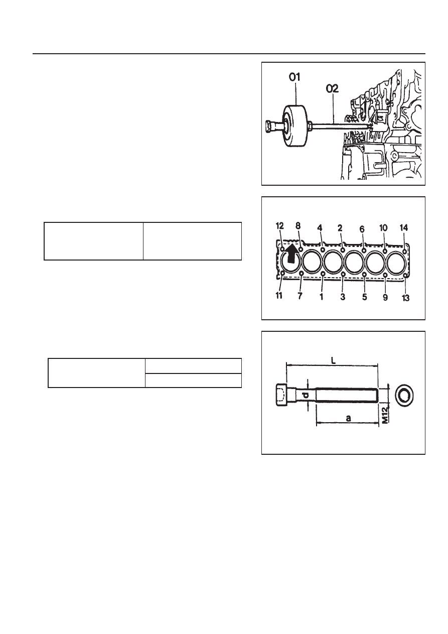
7. Remove the cylinder head bolts in numerical order.
Installation Notice
8. Check the length of the cylinder head bolt.
Installation Notice
Box Wrench Insert 000 589 01 10 00
z
Replace the bolt if the measured length exceed the
max. length.
z
Apply the oil to the thread surface of bolt.
9. Carefully remove the cylinder head and check the mating
surface.
10. Installation should follow the removal procedure in the
reverse order.
6. Remove the guide rail fixing pin from the cylinder head using
the sliding hammer (01) and the threaded pin (02).
Sliding Hammer 116 589 20 33 00
Threaded Pin 116 589 02 34 00
Tightening Torque
1st step 55 Nm
2nd step 90°
3rd step 90°
Length (L)
New 160 ± 0.8 mm
Max. 162 ± 0.7 mm
1B1-38 M162 ENGINE MECHANICAL
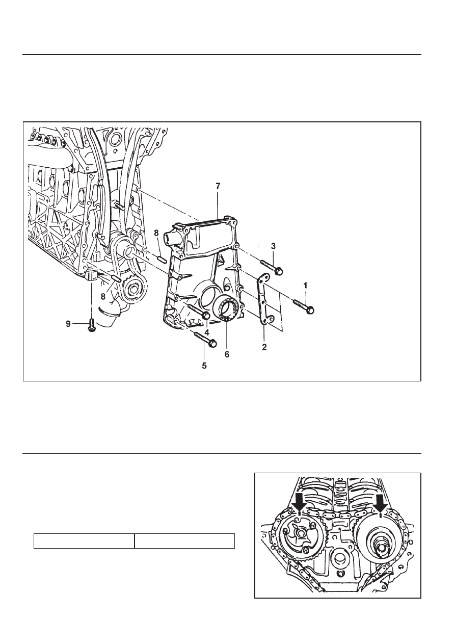
TIMING GEAR CASE COVER
Preceding Work : Removal of cylinder head front cover
Removal of alternator bracket
Removal of tensioning device
Removal of belt pulley and vibration damper
1 Bolt (M8 x 60, 3 pieces) . . . . . 22.5-27.5 Nm
2 A/C Bracket
3 Bolt (M8 x 65, 3 pieces) . . . . . 22.5-27.5 Nm
4 Bolt (M8 x 40, 1 piece) . . . . ... 22.5-27.5 Nm
5 Bolt (M8 x 60, 1 piece) . . . . ... 22.5-27.5 Nm
6 Seal
7 Timing Gear Case Cover
8 Roll Pin
9 Bolt (M6 x 22, 6 pieces) . . . . . . . 9-11 Nm
Removal & Installation Procedure
1. Put the alignment marks (arrows) on the timing chain and
camshaft sprocket.
2. Unscrew the A/C bracket bolts (1) and remove the bracket.
Installation Notice
Tightening Torque
22.5 - 27.5 Nm
Нет комментариевНе стесняйтесь поделиться с нами вашим ценным мнением.
Текст