SsangYong Musso. Manual — part 464
AUTOMATIC TRANSMISSION 5A-33
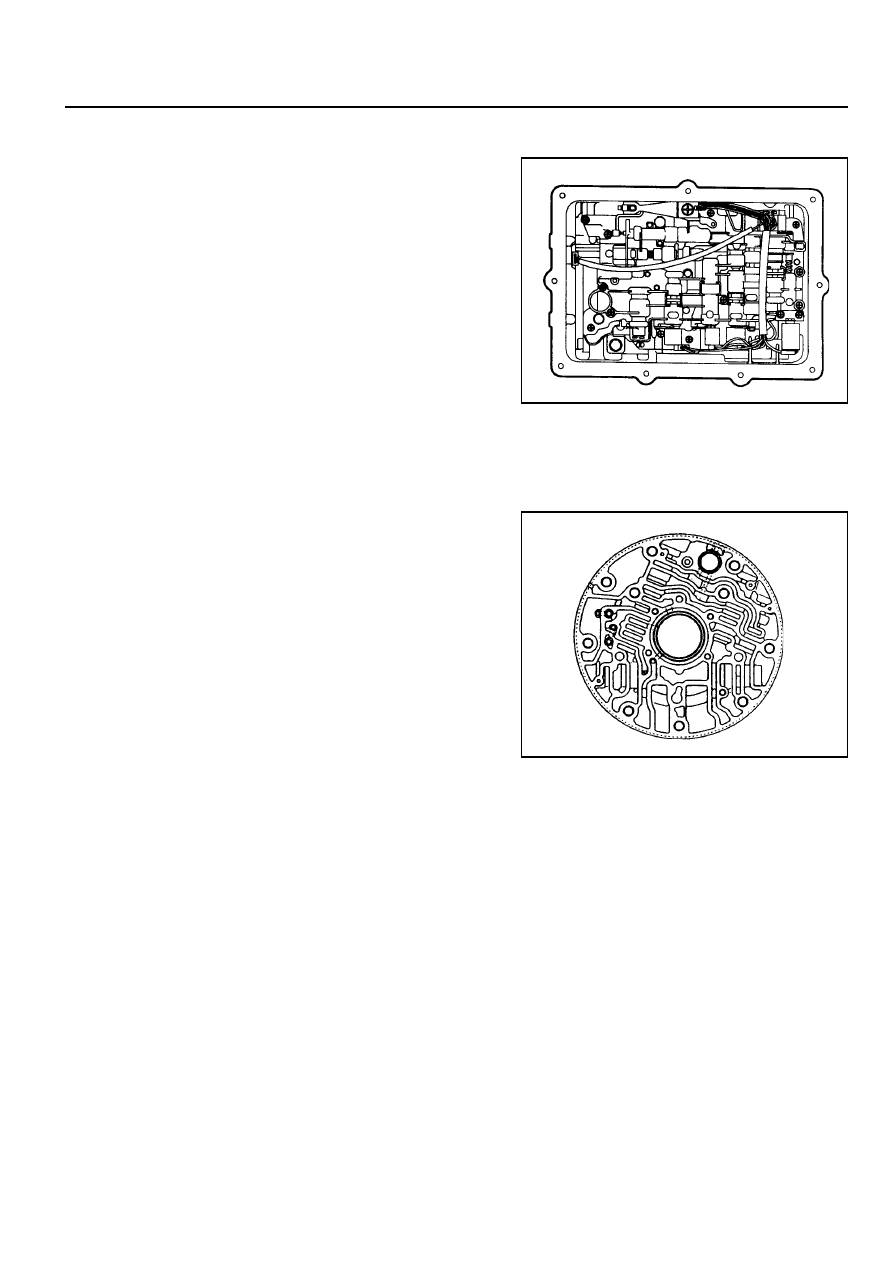
Figure 3.8 - Valve Body
Figure 3.9 - Pump Cover
Valve Body
Figure 3.8 depicts the valve body as a unit as viewed from the
transmission sump. Figure 3.9 depicts the pump cover.
5A-34 AUTOMATIC TRANSMISSION
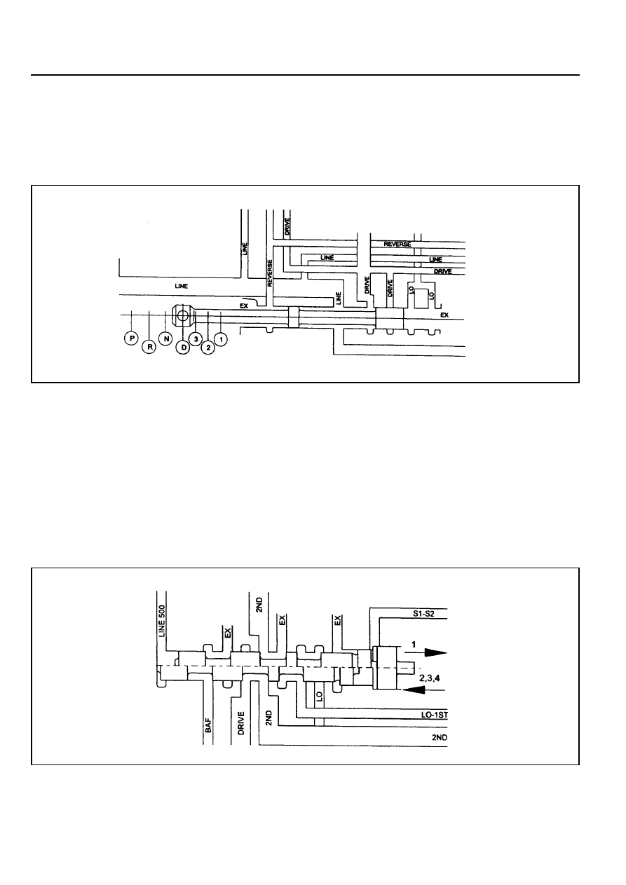
Figure 3.10 - Manual Valve
1-2 Shift Valve
The 1-2 shift valve (refer to figure 3.11) is a two position valve that must be switched to the (2,3,4) position in order to
get any forward gear other than first gear. It is used for all 1-2 and 2-1 gearshifts.
The switching of this valve is achieved by using S1 and/or S2.
During a 1-2 gearshift drive oil from the manual valve passes through to the second gear circuit. During a 2-1
gearshift the band apply feed oil is allowed to exhaust via the 1-2 shift valve.
The 1-2 shift valve works in conjunction with the 3-4 shift valve (described below) to disengage the C4 clutch in first
gear, and engage C4 in second gear. When Manual 1 is selected the C4 clutch and rear band (B2) are engaged.
Figure 3.11 - 1-2 Shift Valve
Manual Valve
The manual valve (refer to figure 3.10) is connected to the vehicle selector mechanism and controls the flow of oil to
the forward and reverse circuits. The manual valve function is identical in all forward gear positions except that in the
Manual 1 position an additional supply of oil is directed to the 1-2 shift valve for application of the rear band and the
C4 overrun clutch.
AUTOMATIC TRANSMISSION 5A-35
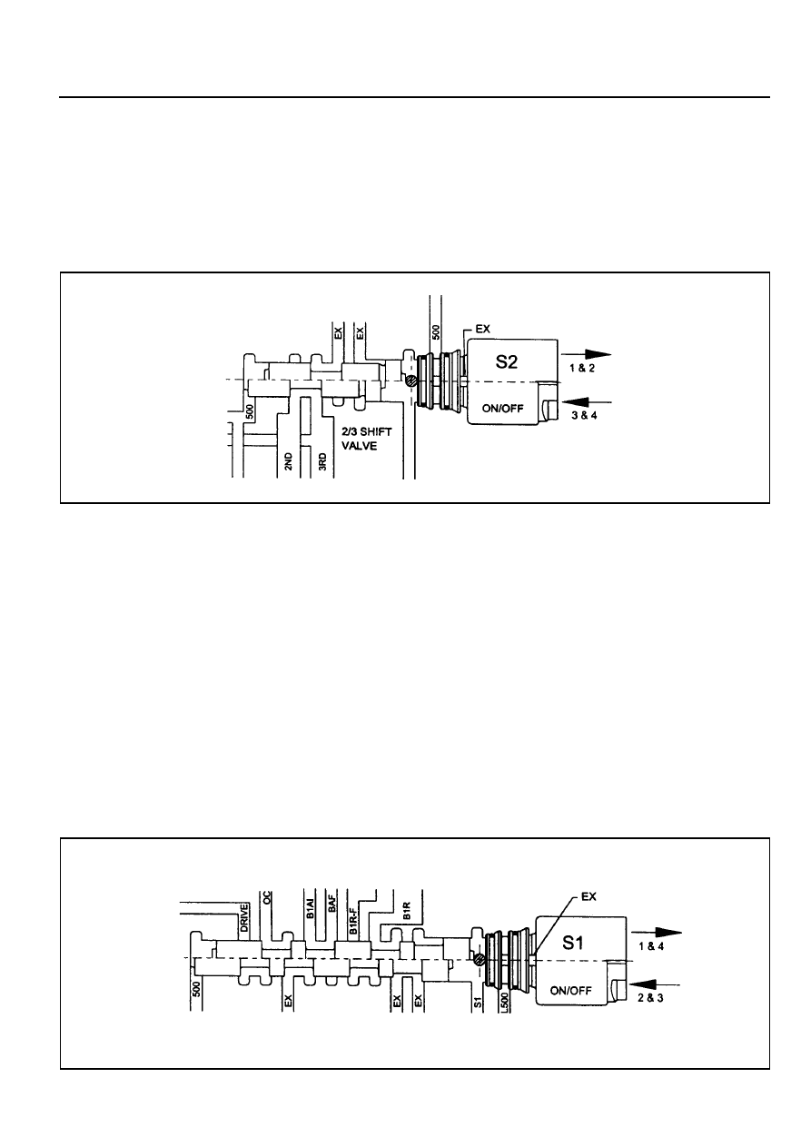
2-3 Shift Valve
The 2-3 shift valve (refer to figure 3.12) is a two position valve. It is used on all 2-3 and 3-2 gearshifts.
The switching of this valve is achieved by S2 which is located at the end of the valve spool.
When in the (1,2) position, second gear oil from the 1-2 shift valve is prevented from entering the third gear circuit.
When the valve is moved to the (3,4) position, oil from the second gear circuit is routed to the third gear circuit and the
transmission changes to third gear.
Figure 3.12 - 2-3 Shift Valve
3-4 Shift Valve
The 3-4 shift valve (refer to figure 3,13) is a two position valve. It is used for all 3-4 and 4-3 gearshifts.
The switching of this valve is achieved by S1 which is located at the end of the valve spool.
During a 3-4 gearshift the 3-4 shift valve:
!
Exhausts the front band release circuit (B 1R) thereby allowing the application of the front band (B1).
!
Connects the inner apply area of the front servo (B 1AI) to the band apply feed circuit (BAF) thus allowing
greater apply forces to the front band.
!
Exhausts the overrun clutch circuit (OC) which allows the C4 clutch to disengage.
During a 4-3 gearshift, the C4 clutch is engaged and the front band (B1) is released. These actions are sequenced
by the 4-3 sequence valve (described below).
The 3-4 shift valve also switches during 1-2 and 2-1 gearshifts (see 1-2 shift valve above) where its function is to
apply the overrun clutch (C4) in second gear but to release it in first gear. Note that the C4 clutch is applied in Manual
1 by virtue of the manual valve and the 1-2 shift valve (as described in the 1-2 shift valve section).
Figure 3.13 - 3-4 Shift Valve
5A-36 AUTOMATIC TRANSMISSION
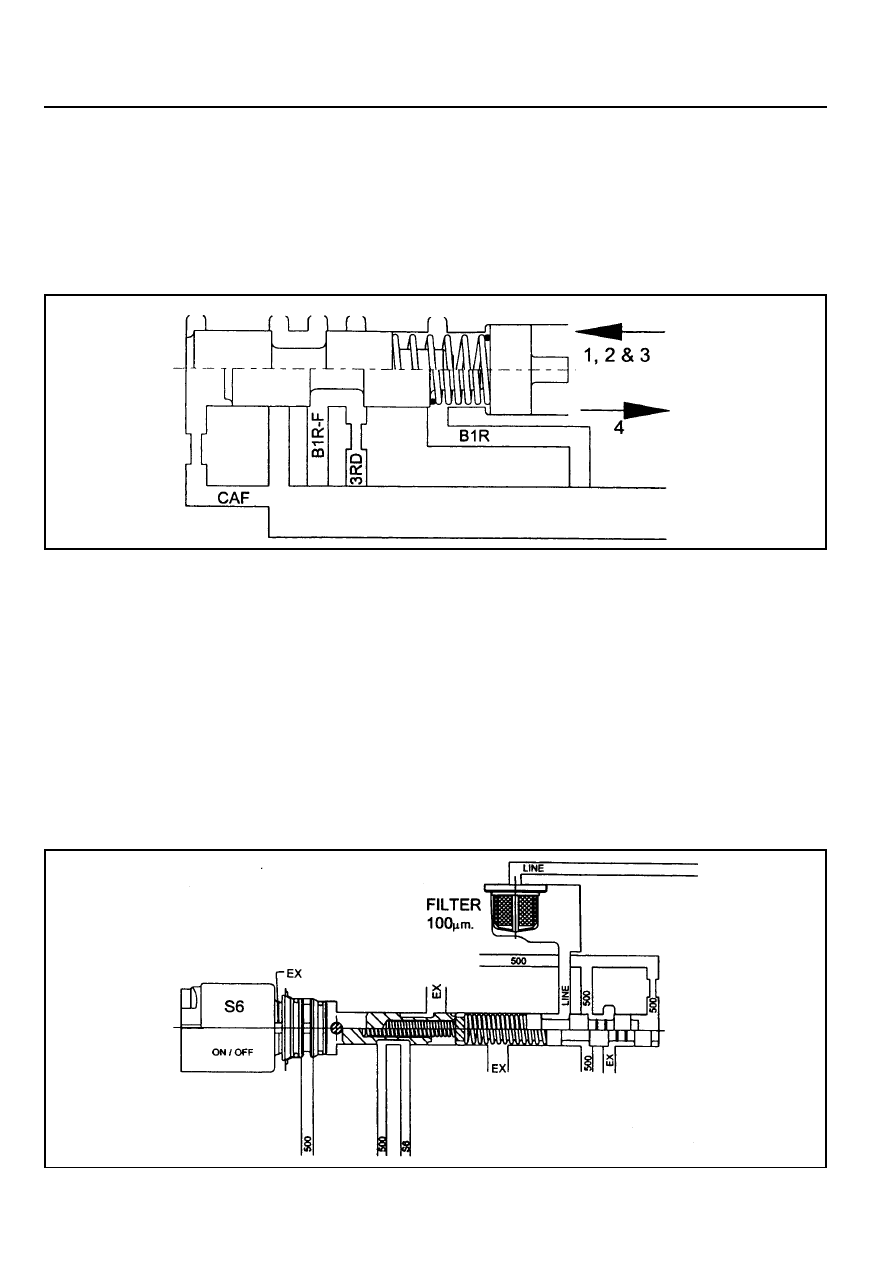
4-3 Sequence Valve
The 4-3 sequence valve (refer figure 3.14) is a two position spring loaded valve. It switches during 3-4 and 4-3
gearshifts although it performs no function during the 3-4 shift.
During the 4-3 shift the 4-3 sequence valve delays the connection of the clutch apply feed circuit (CAF) to the BIR
circuit until the BIR circuit has been fully pressurised by using the third gear circuit. This prevents objectionable
engine flare on completion of the 4-3 gearshift.
Figure 3.14 - 4-3 Sequence Valve
Figure 3.15 - Solenoid Supply Pressure Regulator Valve and Line Pressure Control Valve
Solenoid Supply Pressure Regulator Valve
The solenoid supply valve (refer figure 3.15) supplies a constant pressure to all solenoids (51 to 57). Line pressure
is used as the feed oil to this regulator and the output is termed line 500.
Line Pressure Boost Valve
Line pressure is controlled by 56, which acts as the line pressure boost valve (refer figure 3.15). When 56 pressure
is applied to the end of the PRV it is opposed by spring force and causes LOW line pressure for light throttle
application and cruising.
Heavy throttle application causes the normally open 56 to open (switch Off) thus closing line 500 and opening 56 to
exhaust. Removal of 56 pressure from the PRV results in HIGH line pressure.
Нет комментариевНе стесняйтесь поделиться с нами вашим ценным мнением.
Текст