SsangYong Musso. Manual — part 304

1D2-14 M161 ENGINE COOLING
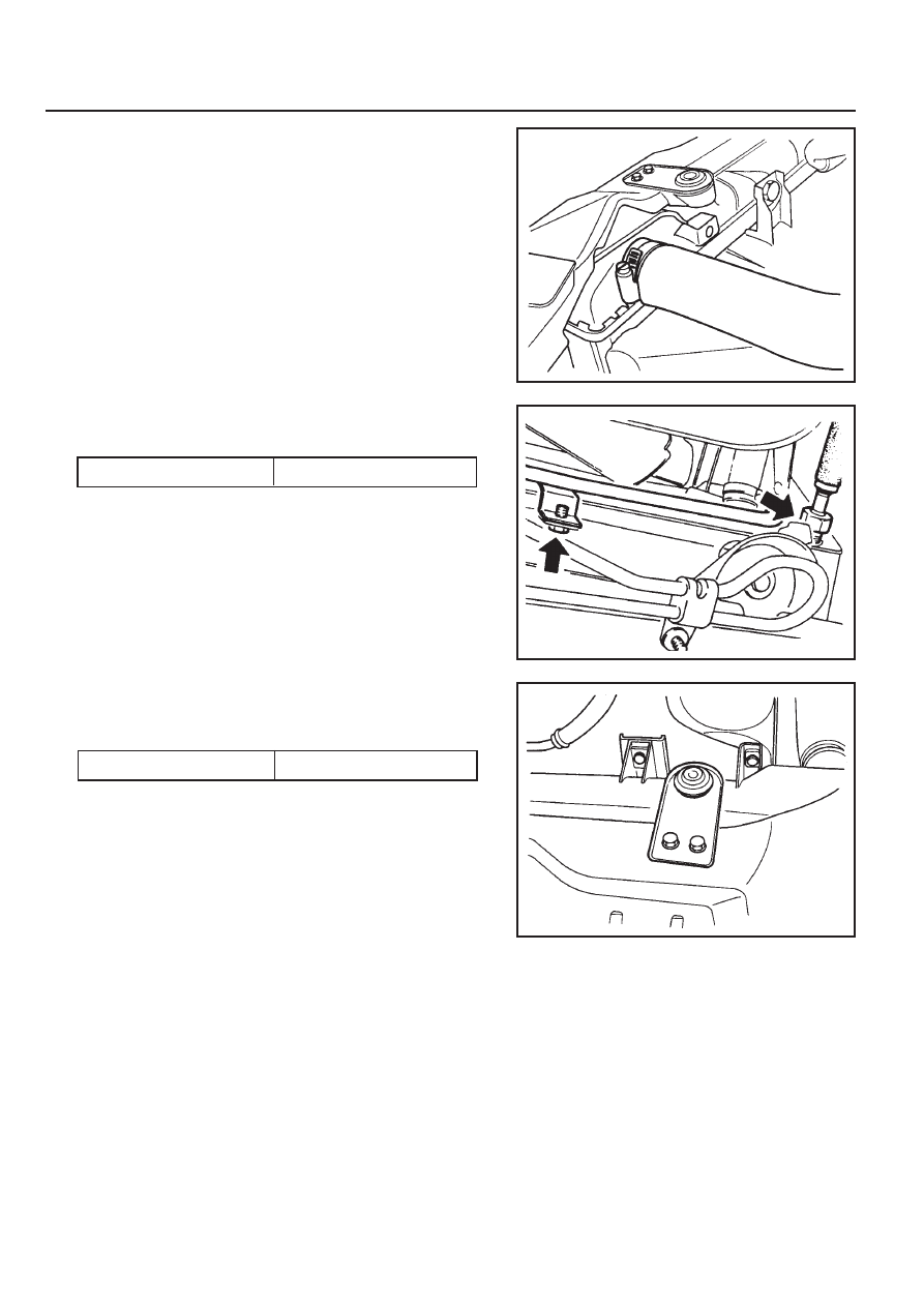
REMOVAL AND INSTALLATION OF COOLING FAN SHROUD
Removal & Installation Procedure
1. Unscrew two bolts from cooling fan shroud and remove
the shrud.
Installation Notice
1 Fan Suroud Assembly
Tightening Torque
3 - 7 Nm
2 Bolt (M6 X 16, 2 pieces) . . . . . . ... 3-7 Nm
2. Installation should follow the removal procedure in the
reverse order.

M161 ENGINE COOLING 1D2-15
REMOVAL AND INSTALLATION OF RADIATOR
Preceding Work : Removal of cooling fan shroud
1 Inlet Hose
2 Hose (to Engine)
3 Hose (to 3-way Connector)
4 Make-up Hose (to Coolant Reservoir)
5 3-way Connector
6 Automatic Transmission Oil Cooling Hose (A/T
Equippend Vehicle)
7 Bolt (M6 X 20, 4 pieces) . . . . . . ... 3-7 Nm
8 Insulator
9 Radiator Bracket
10 Radiator
1D2-16 M161 ENGINE COOLING
Removal & Installation Procedure
1. Drain coolant from the radiator.
2. Remove the coolant thermo connector from the radiator.
3. Remove the each coolant hoses.
Tightening Torque
14 Nm
4. Remove the automatic transmission oil cooling hose.
Installation Notice
5. Unscrew the bolts from radiator bracket and remove the
bracket and insulator.
Installation Notice
Tightening Torque
3 - 7 Nm
6. Remove the radiator upper mounting bolts and then
remove the bracket and insulator.
7. Remove the radiator.
8. Check the radiator pin for crack, damage, leakage and
bending and replace if necessary.
9. Installation should follow the removal procedure in the
reverse order.
10. Berform the cooling system leakage test.

SECTION 1E1
M162 ENGINE ELECTRICAL
Specifications . . . . . . . . . . . . . . . . . . . . . . . 1E1-1
Alternator Specifications . . . . . . . . . . . . . . . . 1E1-1
Starting Motor Specifications . . . . . . . . . . . . 1E1-2
Battery Specifications . . . . . . . . . . . . . . . . . . 1E1-2
Fastener Tightening Specifications . . . . . . . . 1E1-2
Special Tools . . . . . . . . . . . . . . . . . . . . . . . 1E1-3
Special Tools Table . . . . . . . . . . . . . . . . . . . . 1E1-3
Maintenance and Repair . . . . . . . . . . . . . . 1E1-4
On-Vehicle Service . . . . . . . . . . . . . . . . . . . . . 1E1-4
Alternator . . . . . . . . . . . . . . . . . . . . . . . . . . . 1E1-4
Starting Motor . . . . . . . . . . . . . . . . . . . . . . . . 1E1-5
Battery . . . . . . . . . . . . . . . . . . . . . . . . . . . . . 1E1-6
Spark Plug . . . . . . . . . . . . . . . . . . . . . . . . . . 1E1-7
Ignition Cable . . . . . . . . . . . . . . . . . . . . . . . . 1E1-9
Unit Repair . . . . . . . . . . . . . . . . . . . . . . . . 1E1-12
Battery . . . . . . . . . . . . . . . . . . . . . . . . . . . . 1E1-12
SPECIFICATIONS
ALTERNATOR SPECIFICATIONS
CAUTION: Disconnect the negative battery cable before removing or installing any electrical unit or when a
tool or equipment could easily come in contact with exposed electrical terminals. Disconnecting this cable
will help prevent personal injury and damage to the vehicle. The ignition must also be in LOCK unless otherwise
noted.
TABLE OF CONTENTS
Application
Output Voltage
Current
Resistance Between Rotor Core and Slip Ring
Description
12 - 14 V
115 A
∞ Ω
Нет комментариевНе стесняйтесь поделиться с нами вашим ценным мнением.
Текст