SsangYong Actyon Sports II. Manual — part 53

15-9
0000-00
Fuel rail pressure
sensor
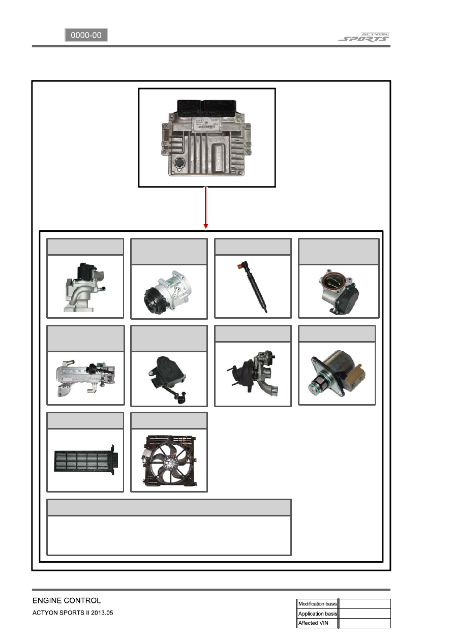
(2) Components for ECU Input
CAN
- ABS & ESP
- GCU
- Instrument
cluster
- TCU
Swirl valve
position sensor
Differential
pressure sensor
E-EGR valve
position sensor
Camshaft position
sensor
Coolant
temperature
sensor
Exhaust gas
temperature
sensor
HFM sensor
Oxygen sensor
T-MAP sensor
Crankshaft
position sensor
Accelerator pedal
sensor
Throttle position
sensor
Knock sensor
-Auto cruise switch
- Rear right wheel
speed (without ABS)
- Refrigerant pressure
sensor
- Clutch pedal signal
- Blower switch signal
- Brake pedal signal
Water sensor
15-10
(3) Components for ECU Output
CAN
E-EGR cooler
bypass valve
- Instrument cluster
- TCU
- Self diagnosis
PTC heater
Cooling fan
E-EGR valve
Variable swirl
valve
E-VGT actuator
IMV valve
A/C compressor
Injector
Throttle position
sensor
- Glow plug unit
- ABS & ESP unit
- GCU
15-11
0000-00
2) ECU Control
(1) Function
a. ECU Function
ECU receives and analyzes signals from various sensors and then modifies those signals into
permissible voltage levels and analyzes to control respective actuators.
ECU microprocessor calculates injection period and injection timing proper for engine piston speed and
crankshaft angle based on input data and stored specific map to control the engine power and emission
gas.
Output signal of the ECU microprocessor drives pressure control valve to control the rail pressure and
activates injector solenoid valve to control the fuel injection period and injection timing; so controls
various actuators in response to engine changes. Auxiliary function of ECU has adopted to reduce
emission gas, improve fuel economy and enhance safety, comforts and conveniences. For example,
there are EGR, booster pressure control, autocruise (export only) and immobilizer and adopted CAN
communication to exchange data among electrical systems (automatic T/M and brake system) in the
vehicle fluently. And Scanner can be used to diagnose vehicle status and defectives.
Operating temperature range of ECU is normally -40 to +85°C and protected from factors like oil,
water and electromagnetism and there should be no mechanical shocks.
To control the fuel volume precisely under repeated injections, high current should be applied instantly
so there is injector drive circuit in the ECU to generate necessary current during injector drive stages.
Current control circuit divides current applying time (injection time) into full-in-current-phase and hold-
current-phase and then the injectors should work very correctly under every working condition.
b. Control Function
Controls by operating stages
To make optimum combustion under every operating stage, ECU should calculate proper injection
volume in each stage by considering various factors.
Starting injection volume control
During initial starting, injecting fuel volume will be calculated by function of temperature and engine
cranking speed. Starting injection continues from when the ignition switch is turned to ignition
position to till the engine reaches to allowable minimum speed.
Driving mode control
If the vehicle runs normally, fuel injection volume will be calculated by accelerator pedal travel and
engine rpm and the drive map will be used to match the drivers inputs with optimum engine power.
-
-
-
15-12
(2) Fuel injection control
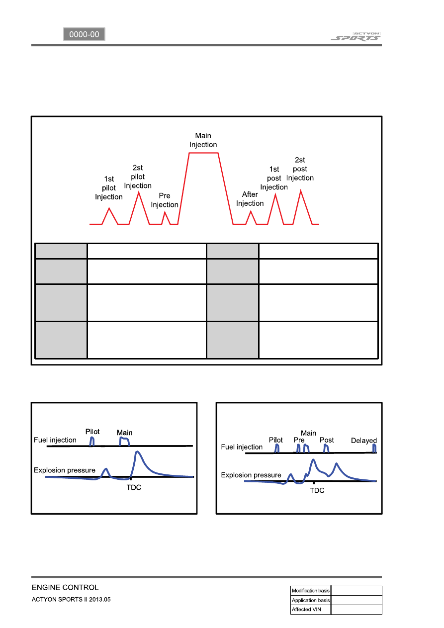
a. Multi injection
Fuel injection process consists of 3 steps: Main Injection, Pilot Injection, Post Injection
Injection
Function
Main
Produces engine power
Pilot 1
Reduces PM by injecting before
main injection.
After
PM control
Pilot 2
Reduces NOx and noise by
shortening main injection delay
due to flammability
Post 1
Reduces PM by enabling fuel
activation.
Pre
Controls NOx emission level,
Combustion noise and
Stable idle
Post 2
Activates CDPF by increasing
exhaust gas temperature and
supplying reduction material
Pilot injection
▶
Multi injection
▶
Нет комментариевНе стесняйтесь поделиться с нами вашим ценным мнением.
Текст