Isuzu D-Max / Isuzu Rodeo (TFR/TFS). Manual — part 1814
MSG MODEL (2WD) 7B-33
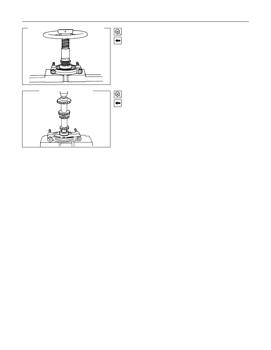
19.Top Gear Shaft
20.Ball Bearing
Use a bench press and the installer to install the ball bearing to
the top gear shaft.
The snap ring groove must be facing the front of the
transmission.
Bearing Installer : 5-8840-0015-0 (J-22912-01)
25.Rear Ball Bearing
Use a bench press and the bearing installer to install the
bearing to the counter gear.
Bearing Installer : 5-8840-0015-0 (J-22912-01)
7B-34 MSG MODEL (2WD)
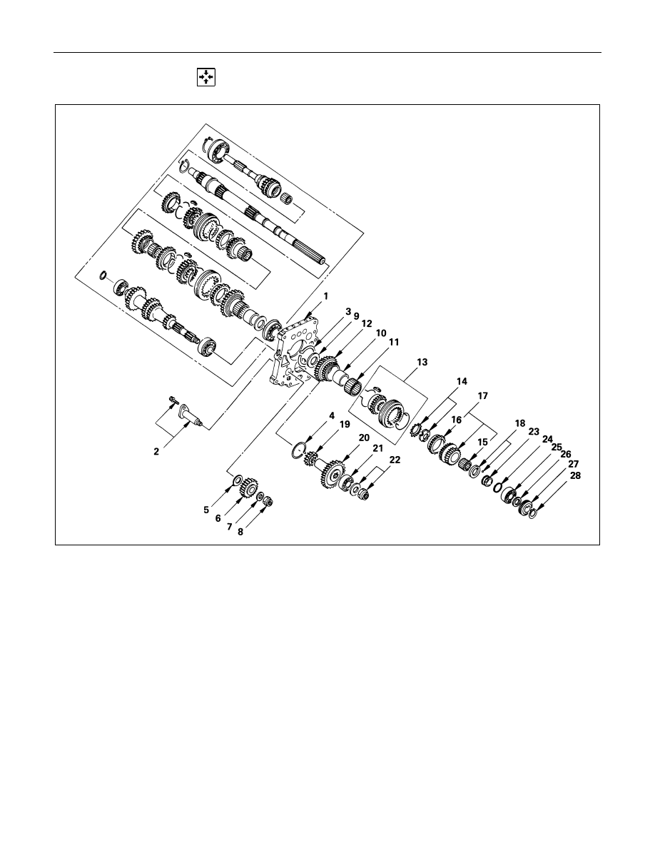
REVERSE GEAR AND 5TH GEAR
Reassembly Steps
! 1. Intermediate plate
! 2. Reverse idler shaft
3. Bearing snap ring
4. Bearing snap ring
5. Thrust washer
! 6. Reverse idler gear
7. Thrust washer
! 8. Counter reverse gear lock nut
! 9. Thrust washer
10. Needle bearing collar
11. Needle bearing
12. Reverse gear
!13. Rev.-5th synchronizer assembly
!14. Mainshaft lock nut and washer
15. Needle bearing
16. 5th block ring
17. 5th gear
!18. Thrust washer and lock ball
19. Counter reverse gear
20. Counter 5th gear
21. Counter end ball bearing
!22. Counter reverse gear nut and washer
!23. Thrust washer thrust ring
!24. Thrust ring snap ring
25. Mainshaft end ball bearing
26. Bearing spacer
27. Speedometer drive gear and lock ball
28. Bearing snap ring
MSG MODEL (2WD) 7B-35
Important Operations
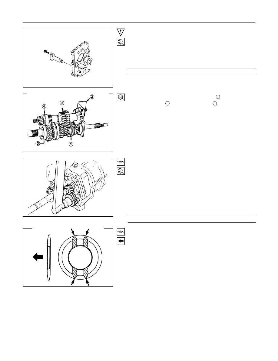
1. Intermediate Plate
2. Reverse Idler Shaft
1) Install the reverse idler shaft to the intermediate plate.
2) Tighten the reverse idler shaft bolt to the specified torque.
Idler Shaft Bolt Torque
N
⋅m(kgf⋅m/lb⋅ft)
18.6
± 3.9 (1.9 ± 0.4 / 13.7 ± 2.9)
3) Set the mainshaft with gear assembly
1
and the counter
gear assembly
2
to the holding fixture
3
.
Holding Fixture : 5-8840-2001-0 (J-29768)
4) Place the holding fixture (with the mainshaft and the counter
shaft) in a vise.
5) Mesh the 3rd-4th synchronizer to the 3rd gear.
Mesh the 1st-2nd synchronizer to the 1st gear.
6) Install the intermediate plate to the mainshaft and the
counter gear ball bearings.
6. Reverse Idler Gear
8. Counter Reverse Gear Lock Nut
1) Apply the engine oil to the idler shaft and the reverse gear
inside circumference.
2) Install the reverse gear to the idler shaft.
3) Install a new counter reverse gear lock nut.
Never reinstall the old lock nut.
4) Tighten the reverse gear lock nut to the specified torque.
Lock Nut Torque
N
⋅m (kgf⋅m/lb⋅ft)
107.8
± 9.8 (11 ± 1.0 / 79.6 ± 7.2)
9. Thrust Washer
1) Apply the engine oil to both sides of the thrust washer.
2) Install the thrust washer to the mainshaft.
The thrust washer oil groove must be facing the reverse
gear side.
7B-36 MSG MODEL (2WD)
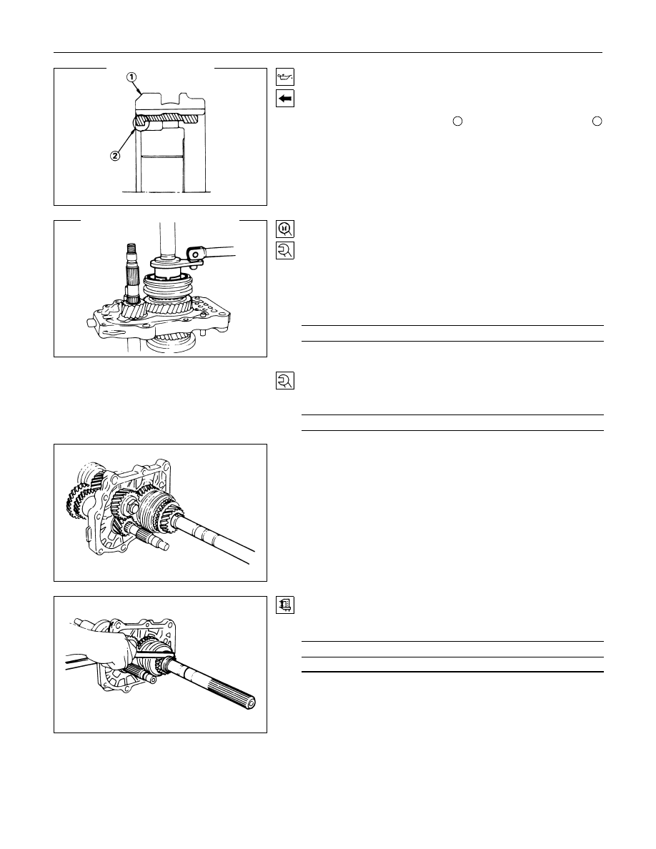
13.Rev.-5th Synchronizer Assembly
1) Apply the engine oil to the clutch hub spline.
2) Install the synchronizer assembly to the mainshaft.
The sleeve heavy chamfer
1
and the insert short side
2
must be facing to the rear side of the transmission.
14.Mainshaft Lock Nut and Washer
1) Install a new lock nut and washer to the mainshaft.
Never reinstall the used lock nut and washer.
2) Use the lock nut wrench to tighten the lock nut to the
specified torque.
Lock Nut Wrench : 5-8840-0353-0 (J-36629)
Lock Nut Torque
N
⋅m(kgf⋅m/lb⋅ft)
107.8
± 9.8 (11 ± 1.0 / 79.6 ± 7.2)
22.Counter Reverse Gear Nut and Washer
Tighten the counter gear lock nut to the specified torque.
Reverse Gear Nut Torque
N
⋅m(kgf⋅m/lb⋅ft)
107.8
± 9.8 (11 ± 1.0 / 79.6 ± 7.2)
18.Thrust Washer and Lock Ball
23.Thrust Washer Thrust Ring
24.Thrust Ring Snap ring
1) Install the thrust washer with lock ball together with the
thrust ring to the mainshaft.
2) Use a pair of snap ring pliers to install the snap ring.
3) Use a thickness gauge to measure the clearance between
the 5th gear and the thrust washer.
5th Gear and Thrust Washer Clearance
mm(in)
Standard
0.1 - 0.3 (0.004 - 0.012)
If required, replace the existing thrust washer with a new
thrust washer to bring the clearance to specification.
Нет комментариевНе стесняйтесь поделиться с нами вашим ценным мнением.
Текст