Isuzu D-Max / Isuzu Rodeo (TFR/TFS). Manual — part 557
6A – 66 ENGINE MECHANICAL
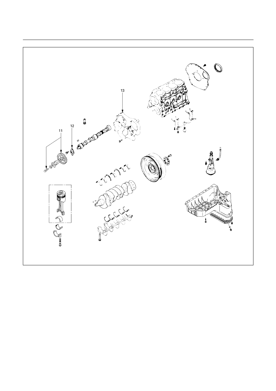
Disassembly Steps-3 (Gear Drive Model)
J
11. Camshaft timing gear
12.
Camshaft thrust plate
13.
Timing gear case
014RY00046
ENGINE MECHANICAL 6A – 67
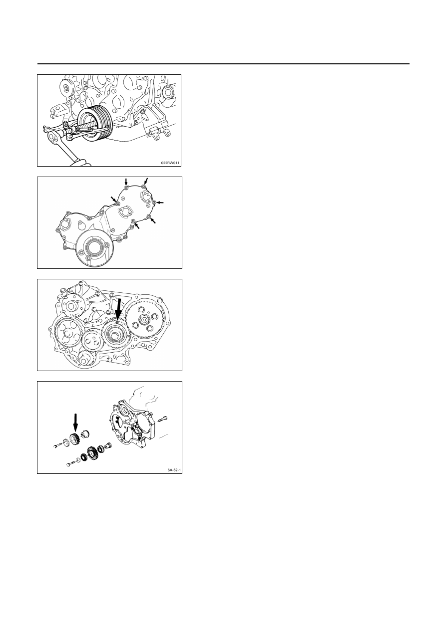
1. Crankshaft
Damper
Pulley
Use the remover to remove the damper pulley
NOTE:
Hold the flywheel ring gear stationary to prevent the
crankshaft from turning when removing the
crankshaft pulley.
4. Timing Gear Case Cover
The timing gear case is tightened together with the
injection pump at the 6 points indicated by the arrows in
the illustration.
6a. Idle Gear B (4JA1TC, 4JH1TC only)
Install lock bolts to the holes marked with an arrow in the
illustration to hold the gear in place. Remove the gear.
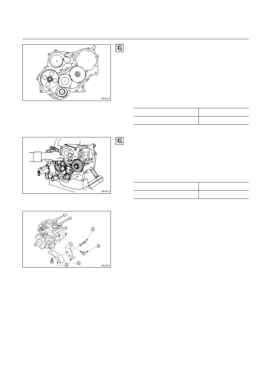
7. Idler
Gear
“A”
1. Measure the camshaft timing gear backlash and the
crankshaft timing gear backlash before removing the
idler gear.
2. Measure the idler gear end play before removing the
idler gear.
Note:
Refer to the following items for details on the
backlash and end play measurement procedures.
6A – 68 ENGINE MECHANICAL
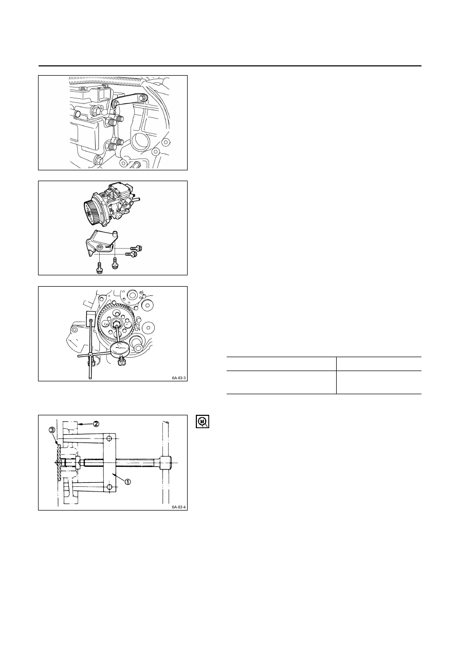
Timing Gear Backlash Measurement
1) Set a dial indicator to the timing gear to measured.
Hold both the gear to be checked and the adjusting
gear stationary.
2) Move the gear to be checked as far as possible to
both the right and the left.
Take the dial indicator reading.
If the measured value exceeds the specified limit, the
timing gear must be replaced.
Timing Gear Backlash
mm (in)
Standard
Limit
0.10 – 0.17 (0.0039 – 0.0067)
0.30 (0.012)
Idler Gear “A” End Play Measurement
Insert a feeler gauge between the idler gear and the thrust
collar to measure the gap and determine the idler gear
end play.
If the measured value exceeds the specified limit, the
thrust collar must be replaced.
Idler Gear End Play
mm (in)
Standard
Limit
0.07
(0.0028)
0.2
(0.0079)
10. Injection Pump
1 Remove the injection pump rear bracket bolts
R
from
the injection pump bracket
S
.
2 Remove the injection pump rear bracket bolts
T
and
the bracket
U
from the cylinder body.
3. Pull the injection pump along with the injection pump
timing gear free toward the rear of the engine.
ENGINE MECHANICAL 6A – 69
4JA1TC, 4JH1TC
1 Remove the injection pump upper bracket from the
injection pump.
2 Remove the injection pump bottom bracket from the
injection pump.
3 Pull the injection pump along with the injection pump
timing gear free toward the rear of the engine.
Note:
Plug the injection pump delivery holder ports with the
shipping caps (or the equivalent) to prevent the entry
of foreign material.
11. Camshaft Timing Gear
1. Use a dial indicator to measure the camshaft end play.
This must be done before removing the camshaft
gear.
If the camshaft end play exceeds the specified limit,
the thrust plate must be replaced.
Camshaft End Play
mm (in)
Standard
Limit
0.050
–
0.114
(0.002 – 0.0044)
0.20
(0.008)
2. Remove the camshaft timing gear bolt from the
camshaft.
Note:
Hold the camshaft stationary to prevent the camshaft
from turning.
3. Use the universal puller
Q
to pull out the camshaft
timing gear
R
.
Universal Puller: 5-8521-0002-0
4. Remove the thrust plate
S
.
080L200005
080L200006
Нет комментариевНе стесняйтесь поделиться с нами вашим ценным мнением.
Текст