Isuzu D-Max / Isuzu Rodeo (TFR/TFS). Manual — part 555

6A – 58 ENGINE MECHANICAL
Disassembly Steps-2 (Belt Drive Model)
10.
Crankshaft damper pulley
15.
Timing belt tension adjusting
11.
Timing pulley housing upper
Lever
cover
16.
Timing belt tensioner
12.
Timing pulley housing lower
17.
Timing belt
Cover
18.
Tension
idler
13.
Water pump
J
19. Crankshaft timing pulley center
14.
Camshaft timing pulley flange
J
20. Crankshaft timing pulley
J
21. Injection pump timing pulley
J
22. Injection pump
ENGINE MECHANICAL 6A – 59
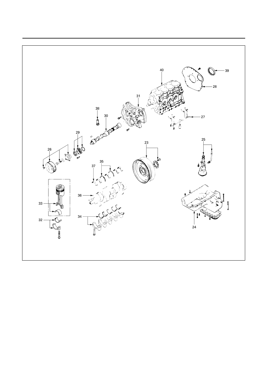
Disassembly Steps-3 (Belt Drive Model)
J
23.
Flywheel
J
33.
Piston and connecting road with
24.
Oil pan
upper bearing
25.
Oil pump with oil pipe
J
34.
Crankshaft bearing cap with
26.
Camshaft timing pulley
lower bearing
J
27. Piston cooling oil pipe
35.
Crankshaft thrust bearing
28.
Cylinder body rear plate
36.
Crankshaft
29.
Oil seal retainer
J
37. Crankshaft upper bearing
J
30. Camshaft
J
38. Tappet
31.
Timing pulley housing
J
39. Crankshaft rear oil seal
J
32. Connecting rod bearing cap with
40.
Cylinder body
lower
bearing
014RY00045

6A – 60 ENGINE MECHANICAL
Important Operations
4. Injection
Nozzle
Holder
1. Remove the nozzle holder bracket nuts.
2. Use the nozzle holder remover and the sliding hammer
to remove the nozzle holder together with the holder
bracket.
Nozzle Holder Remover: 5-8840-2034-0
Sliding Hammer:
5-8840-0019-0
6. Rocker Arm Shaft and Rocker Arm
Loosen the rocker arm shaft bracket bolts in numerical
order a little at a time.
Note:
Failure to loosen the rocker arm shaft bracket bots in
numerical order a little at a time will adversely affect
the rocker arm shaft.
8. Cylinder
Head
Loosen the cylinder head bolts in numerical order a little at
a time.
Note:
Failure to loosen the cylinder head bolts in numerical
order a little at a time will adversely affect the cylinder
head lower surface.
19. Crankshaft Timing Pulley Center
1. Use the fixing wrench to prevent the cranksahft from
turning.
Fixing Wrench: 5-8840-0161-0
2. Remove the timing pulley center from the crankshaft.

ENGINE MECHANICAL 6A – 61
20. Camshaft Timing Pulley
1. Install the stopper bolt
Q
to the timing pulley to
prevent it from turning.
21. Injection Pump Timing Pulley
1. Install the stopper bolt
Q
to the timing pulley to
prevent it from turning.
2. Use the timing pulley remover
R
to remove the
injection pump timing pulley.
Timing Pulley Puller: 5-8840-0086-0
3. Remove the stopper bolt.
22. Injection Pump
1. Remove the three injection pump bracket nuts
Q
at
the rear of the timing pulley housing.
2. Remove the injection pump rear bracket bolts
R
from
the injection pump bracket
S
.
3. Remove the injection pump rear bracket bolts
T
and
the bracket
U
from the cylinder body.
4. Pull the injection pump free toward the rear of the
engine.
Note:
Plug the injection pump delivery holder ports with the
shipping caps (or the equivalent) to prevent the entry
of foreign material.
Нет комментариевНе стесняйтесь поделиться с нами вашим ценным мнением.
Текст