Isuzu D-Max / Isuzu Rodeo (TFR/TFS). Manual — part 877
6E–237
3.2L ENGINE DRIVEABILITY AND EMISSIONS
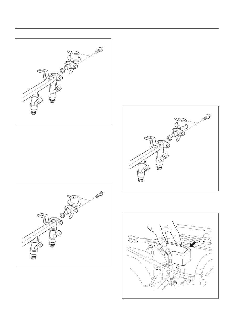
6. Remove the fuel pressure regulator attaching screw.
060RW116
7. Remove the fuel pressure regulator from the fuel rail.
Disassembly Procedure
1. Remove the O-ring from the fuel pressure regulator.
2. Loosen the swivel nut.
3. Remove the fuel return line from the fuel pressure
regulator.
4. Remove the O-ring from the fuel return line.
D
The O-ring may be left inside the fuel pressure
regulator instead of on the fuel return line.
060RW116
Assembly Procedure
1. Install a new O-ring on the fuel return line.
2. Install the fuel return line on the fuel pressure
regulator.
NOTE: Do not over-tighten the swivel nut on the fuel
pressure regulator. The fuel pressure regulator can be
damaged and fuel may leak if the swivel nut is
over-tightened.
3. Tighten the swivel nut.
4. Install a new O-ring on the fuel pressure regulator.
Installation Procedure
1. Install the fuel pressure regulator attaching screw.
Tighten
D
Tighten the fuel pressure regulator attaching
screw to 3 N·m (0.3 kg·m/26 lb in.).
060RW116
2. Install the fuel pressure regulator on the fuel rail.
3. Install the two bolts to the protector that secures the
common chamber.
060RW066

6E–238 3.2L ENGINE DRIVEABILITY AND EMISSIONS
4. Install the pressure regulator hose to the fuel
pressure regulator.
5. Install the fuel pump relay. Refer to
Fuel Pump Relay.
6. Connect the negative battery cable.
7. Crank the engine until it starts. Cranking the engine
may take longer than usual due to trapped air in the
fuel lines.
Fuel Metering System
Fuel Pressure Relief Procedure
CAUTION: To reduce the risk of fire and personal
injury, it is necessary to relieve the fuel system
pressure before servicing the fuel system
components.
CAUTION: After relieving the system pressure, a
small amount of fuel may be released when servicing
fuel lines or connections. Reduce the chance of
personal injury by covering the fuel line fittings with
a shop towel before you disconnect the fittings. The
towels will absorb any fuel that may leak out. When
the disconnect is completed, place the towel in an
approved container.
1. Remove the fuel cap.
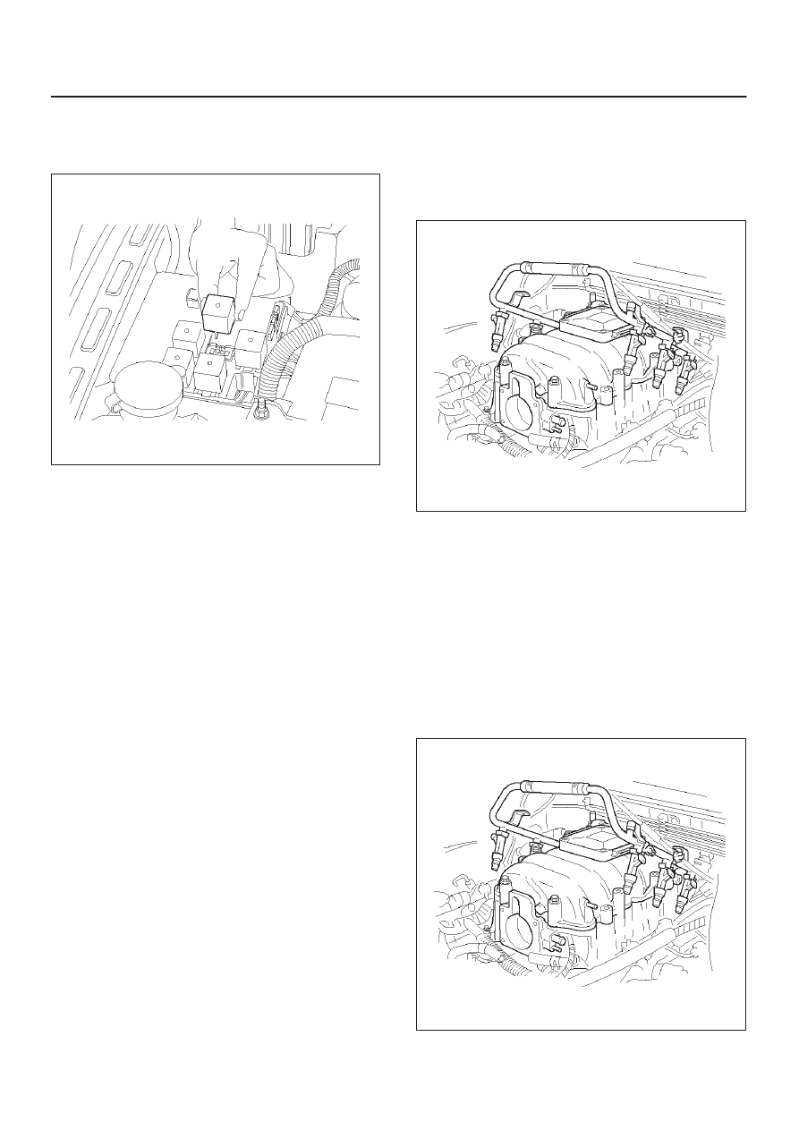
2. Remove the fuel pump relay from the underhood
relay box. Refer to
Fuel Pump Relay.
060RW067
3. Start the engine and allow it to stall.
4. Crank the engine for 30 seconds.
5. Disconnect the negative battery cable.
Fuel Pump Assembly
Removal Procedure
Refer to
Fuel Tank In Fuel Pump Relay.
060RW068
Fuel Pump Relay
Removal Procedure
1. Remove the fuse and relay box cover from under the
hood.
2. Consult the diagram on the cover to determine which
is the correct relay.
3. Pull the relay straight up and out of the fuse and relay
box.
060RW067
6E–239
3.2L ENGINE DRIVEABILITY AND EMISSIONS
Installation Procedure
1. Insert the relay into the correct place in the fuse and
relay box with the catch slot facing forward.
060RW067
2. Press down until the catch engages.
D
An audible “click” will be heard.
3. Install the fuse and relay box cover.
Fuel Rail Assembly
Removal Procedure
NOTE:
D
Do not attempt to remove the fuel inlet fitting on the
fuel rail. It is staked in place. Removing the fuel inlet
fitting will result in damage to the fuel rail or the
internal O-ring seal.
D
Use care when removing the fuel rail assembly in
order to prevent damage to the injector electrical
connector terminals and the injector spray tips.
D
Fittings should be capped and holes plugged during
servicing to prevent dirt and other contaminants from
entering open lines and passages.
IMPORTANT:
Before removal, the fuel rail assembly
may be cleaned with a spray type engine cleaner. Follow
the spray package instructions. Do not immerse the fuel
rails in liquid cleaning solvent.
1. Depressurize the fuel system. Refer to Fuel Pressure
Relief Procedure in this Section.
2. Disconnect the negative battery cable.
3. Remove the engine cover.
4. Disconnect the accelerator pedal cable from throttle
body and cable bracket.
5. Disconnect the connectors from, solenoid valve,
sensing valve.
6. Disconnect the vacuum hose on canister VSV and
positive crankcase ventilation hose.
7. Remove the common chamber Refer to the common
chamber in Engine Mechanical.
1) Lift up carefully on the fuel injectors. Do not
separate the fuel injectors from the fuel rail.
2) If an injector becomes separated from the fuel rail,
the infector O-ring seals and the retainer clip must
be replaced.
3) Drain residual fuel into an approved container.
060RW044
8. If removal of the fuel pressure regulator is necessary,
refer to
Fuel Pressure Regulator.
9. If removal of the fuel injectors is necessary, refer to
Fuel Injectors.
Installation Procedure
1. If the fuel injectors were removed, install them. Refer
to
Fuel Injectors.
2. If the fuel pressure regulator was removed, install it.
Refer to
Fuel Pressure Regulator.
3. Install the common chamber.Refer to common
chamber in engine Mechanical.
060RW044
6E–240 3.2L ENGINE DRIVEABILITY AND EMISSIONS
4. Connect the vacuum hose on Canister VSV and
positive crankcase ventilation hose.
5. Connect the connectors to, solenoid valve.
6. Connect the accelerator pedal cable to throttle body
and cable bracket.
7. Install the engine cover.
8. Connect the negative battery cable.
9. Crank the engine until it starts. Cranking the engine
may take longer than usual due to trapped air in the
fuel rail and in the injectors.
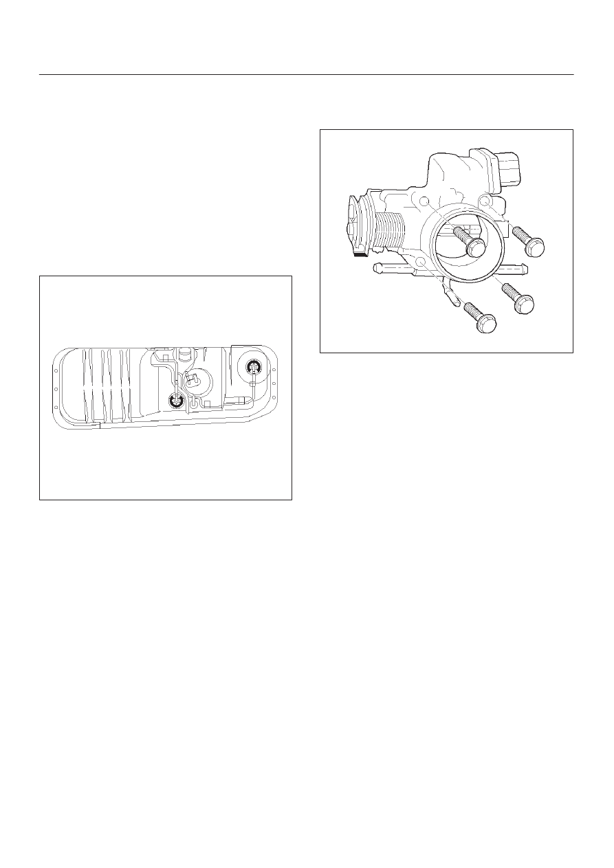
Fuel Tank
Removal Procedure
Refer to
Fuel Tank In Fuel Pump Relay.
060RW068
Throttle Body (TB)
Removal Procedure
1. Disconnect the negative battery cable.
2. Drain the cooling system. Refer to
Cooling System.
3. Remove the accelerator cable assembly. Refer to
Accelerator Cable in Engine Speed Control System..
4. Disconnect the electrical connectors:
D
Throttle position (TP) sensor.
D
Idle air control (IAC) solenoid.
D
Intake air temperature (IAT) sensor. Refer to
Intake
Air Temperature Sensor.
5. Disconnect the vacuum hose below the air horn.
6. Remove the intake air duct clamp.
7. Disconnect the intake air duct.
8. Disconnect the coolant lines from the throttle body.
9. Remove the bolts from the common chamber.
10. Remove the throttle body from the common chamber.
11. Remove the gasket from the upper intake manifold.
060RW065
12. Remove the IAC. Refer to
Idle Air Control (IAC)
Solenoid.
13. Remove the TP sensor. Refer to
Throttle Position
(TP) Sensor.
Inspection Procedure
NOTE: Do not use solvent of any type when you clean the
gasket surfaces on the intake manifold and the throttle
body assembly. The gasket surfaces and the throttle
body assembly may be damaged as a result.
D
If the throttle body gasket needs to be replaced,
remove any gasket material that may be stuck to the
mating surfaces of the manifold.
D
Do not leave any scratches in the aluminum casting.
Installation Procedure
1. Install the TP sensor. Refer to
Throttle Position (TP)
Sensor.
2. Install the IAC. Refer to
Idle Air Control (IAC)
Solenoid.
3. Install the gasket on the common chamber.
4. Install the throttle body on the common chamber.
5. Secure the gasket and the throttle body with the four
bolts.
D
The vacuum lines must be properly routed under
the throttle body before tightening the mounting
bolts.
Нет комментариевНе стесняйтесь поделиться с нами вашим ценным мнением.
Текст