Isuzu D-Max / Isuzu Rodeo (TFR/TFS). Manual — part 878
6E–241
3.2L ENGINE DRIVEABILITY AND EMISSIONS
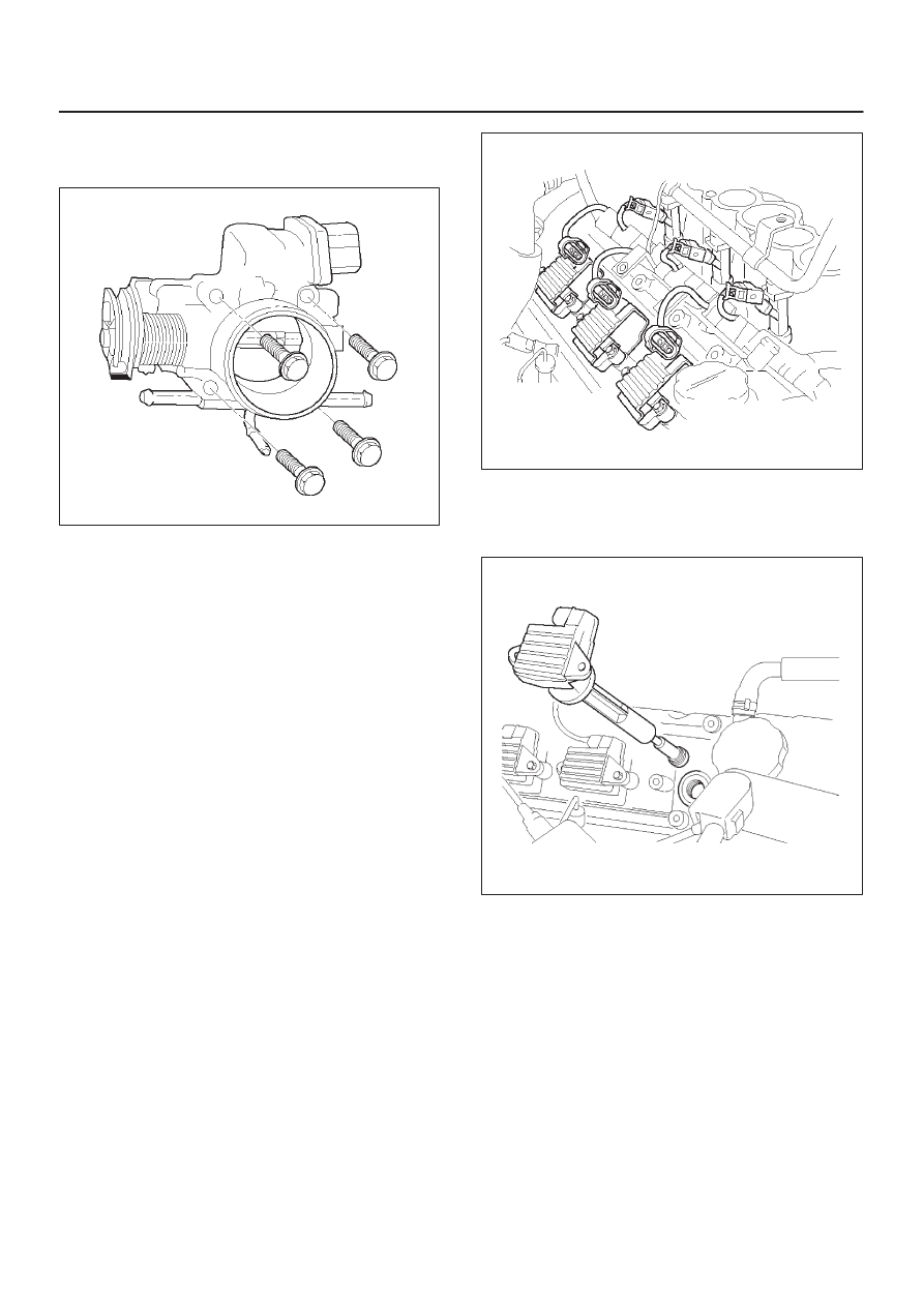
Tighten
D
Tighten the throttle body mounting bolts to 24
N·m (2.4 kg·m/17 lb ft.).
060RW065
6. Install the coolant lines.
7. Connect all the vacuum lines.
8. Install the intake air duct.
9. Tighten the intake air duct clamp.
10. Connect all the electrical connectors:
D
Throttle position (TP) sensor.
D
Idle air control (IAC) solenoid.
D
Intake air temperature (IAT) sensor. Refer to
Intake
Air Temperature Sensor.
11. Install the accelerator cable assembly. Refer to
Accelerator Cable in Engine Speed Control System..
12. Fill the cooling system. Refer to
Cooling System.
13. Install the negative battery cable.
Electronic Ignition System
Removal Procedure
1. Disconnect the negative battery cable.
2. Disconnect the electrical connector at the coil
module.
3. Remove the two screws that secure the coil module to
the rocker cover.
014RW108
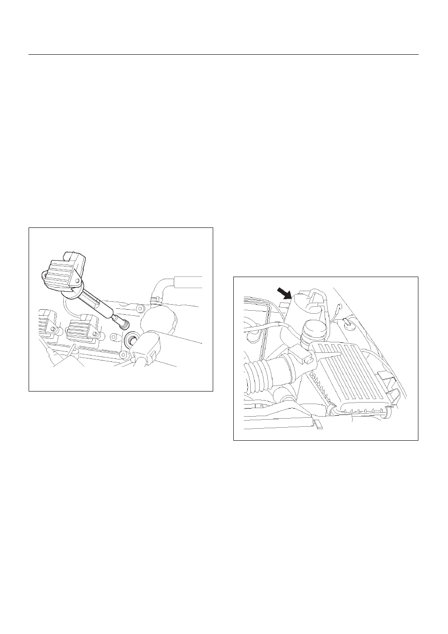
4. Remove the coil module and the spark plug boot from
the spark plug.
D
Twist the coil module while pulling it straight up.
060RW117
5. Use the spark plug socket in order to remove the
spark plug from the engine.
Spark Plug Gap Check
D
Check the gap of all spark plugs before installation.
D
Use a round wire feeler gauge to ensure an accurate
check.
D
Plugs installed with the wrong gap can cause poor
engine performance and excessive emissions.
6E–242 3.2L ENGINE DRIVEABILITY AND EMISSIONS
Installation Procedure
NOTE: The plug must thread smoothly into the cylinder
head and be fully seated. Use a thread chaser if
necessary to clean the threads in the cylinder head.
Cross-threading or failure to fully seat the spark plug can
cause plug overheating, exhaust blow-by gases, or
thread damage. Do not overtighten the spark plugs. Over
tightening can cause aluminum threads to strip.
1. Install the spark plug in the engine. Use the
appropriate spark plug socket.
Tighten
D
Tighten the spark plug to 18 N·m
(1.8 kg·m/13 lb ft.).
2. Install the coil module and spark plug boot over the
spark plug.
3. Secure the coil module to the rocker cover with two
screws.
060RW117
4. Connect the electrical connector at the coil module.
5. Connect the negative battery cable.
Catalytic Converter
Removal and Installation Procedure
Refer to
Engine Exhaust in Engine.
Air Conditioning Relay
Removal Procedure
1. Remove the fuse and relay box cover from under the
hood.
2. Consult the diagram on the cover to determine which
is the correct relay.
3. Pull the relay straight up and out of the fuse and relay
box.
Installation Procedure
1. Insert the relay into the correct place in the fuse and
relay box with the catch slot facing forward.
2. Press down until the catch engages.
D
An audible “click” will be heard.
3. Install the fuse and relay box cover.
EVAP Canister Hoses
Service Information
To view the routing of the EVAP canister hoses, refer to
Vehicle Emission Control Information in Diagnosis. Use
6148M or equivalent when you replace the EVAP canister
hoses.
EVAP Canister
Removal Procedure
1. Disconnect the negative battery cable.
2. Disconnect the hose from the EVAP canister.
060RW073
3. Remove the EVAP canister to the mounting bracket.
Inspection Procedure
1. Inspect the hoses for cracks and leaks.
2. Inspect the canister for a damaged case.
Installation Procedure
1. Slide the canister into mounting bracket the install the
mounting bracket bolt.

6E–243
3.2L ENGINE DRIVEABILITY AND EMISSIONS
2. Install the EVAP canister to the mounting bracket.
060RW073
3. Connect the two hoses to the EVAP canister.
4. Disconnect the negative battery cable.
EVAP Canister Purge Solenoid
Removal Procedure
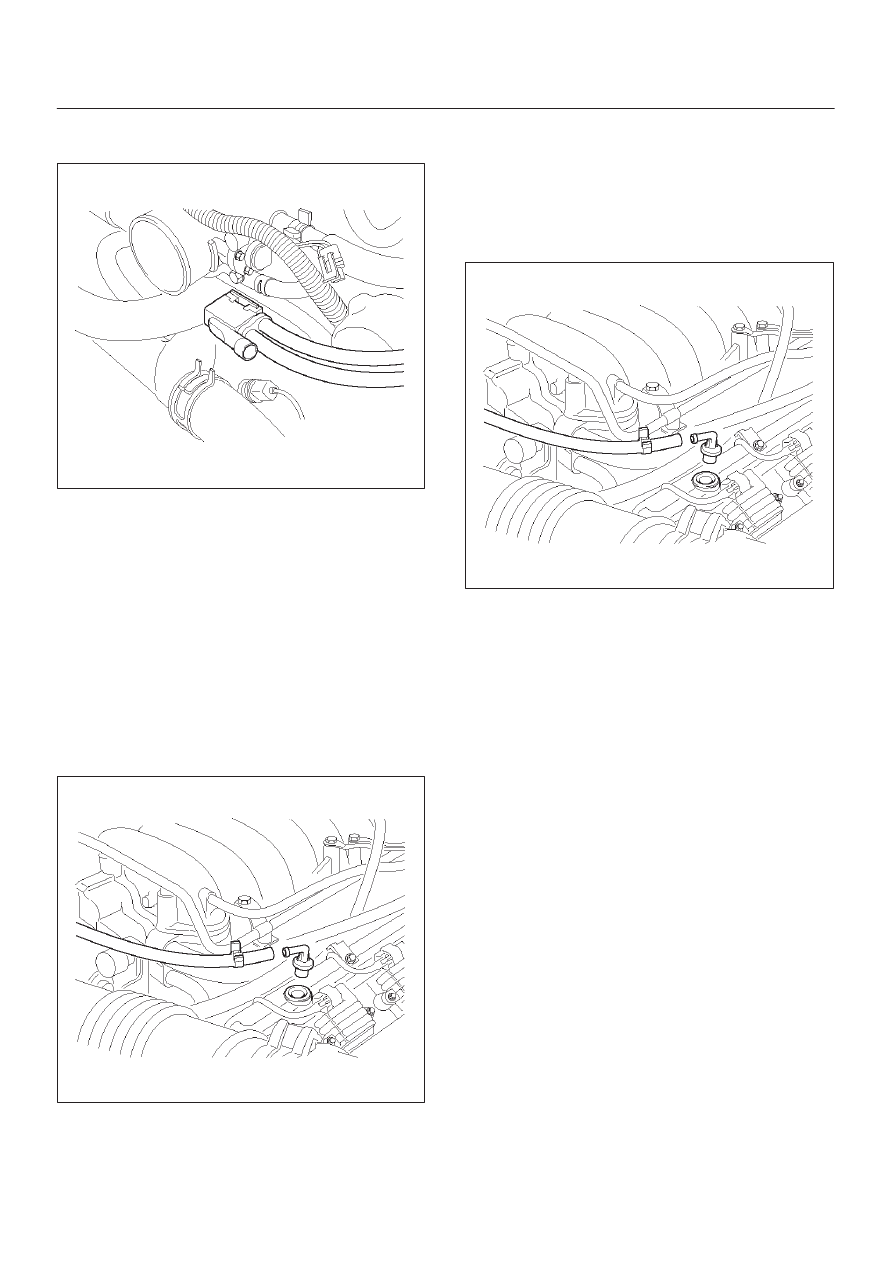
1. Disconnect the electrical connector from the EVAP
canister purge solenoid.
2. Disconnect the vacuum hoses from the EVAP
canister purge solenoid.
014RW136
3. Remove the EVAP canister purge solenoid retaining
bolt from the upper intake manifold.
4. Remove the EVAP canister purge solenoid.
014RW137
Installation Procedure
1. Install the EVAP canister purge solenoid on the upper
intake manifold.
2. Install the EVAP canister purge solenoid retaining
bolt.
3. Connect the vacuum hoses to the EVAP canister
purge solenoid.
014RW137
6E–244 3.2L ENGINE DRIVEABILITY AND EMISSIONS
4. Connect the electrical connector to the EVAP canister
purge solenoid.
014RW138
Fuel Tank Vent Valve
Removal and Installation Procedure
Refer to
Fuel Pump
Positive Crankcase Ventilation
(PCV) Valve
Removal Procedure
1. Remove the vacuum hose at the PCV valve.
D
Slide the clamp back to release the hose.
2. Pull the PCV valve from the rubber grommet in the
right valve cover.
014RW097
Inspection Procedure
1. Shake the valve and listen for the rattle of the needle
inside the valve.
2. If the valve does not rattle, replace the valve.
Installation Procedure
1. Push the PCV valve into the rubber grommet in the
left valve cover.
2. Install the vacuum hose on the PCV valve and secure
the vacuum hose with the clamp.
014RW097
Wiring and Connectors
Wiring Harness Service
The control module harness electrically connects the
control module to the various solenoids, switches and
sensors in the vehicle engine compartment and
passenger compartment.
Replace wire harnesses with the proper part number
replacement.
Because of the low amperage and voltage levels utilized
in powertrain control systems, it is essential that all wiring
in environmentally exposed areas be repaired with crimp
and seal splice sleeves.
The following wire harness repair information is intended
as a general guideline only. Refer to
Chassis Electrical for
all wire harness repair procedures.
Connectors and Terminals
Use care when probing a connector and when replacing
terminals. It is possible to short between opposite
terminals. Damage to components could result. Always
use jumper wires between connectors for circuit
checking. NEVER probe through Weather-Pack seals.
Use an appropriate connector test adapter kit which
contains an assortment of flexible connectors used to
probe terminals during diagnosis. Use an appropriate
fuse remover and test tool for removing a fuse and to
adapt the fuse holder to a meter for diagnosis.
Open circuits are often difficult to locate by sight because
oxidation or terminal misalignment are hidden by the
connectors. Merely wiggling a connector on a sensor, or
in the wiring harness, may temporarily correct the open
circuit. Intermittent problems may also be caused by
oxidized or loose connections.
Нет комментариевНе стесняйтесь поделиться с нами вашим ценным мнением.
Текст