Isuzu D-Max / Isuzu Rodeo (TFR/TFS). Manual — part 255
ENGINE DRIVEABILITY AND EMISSIONS
6E–261
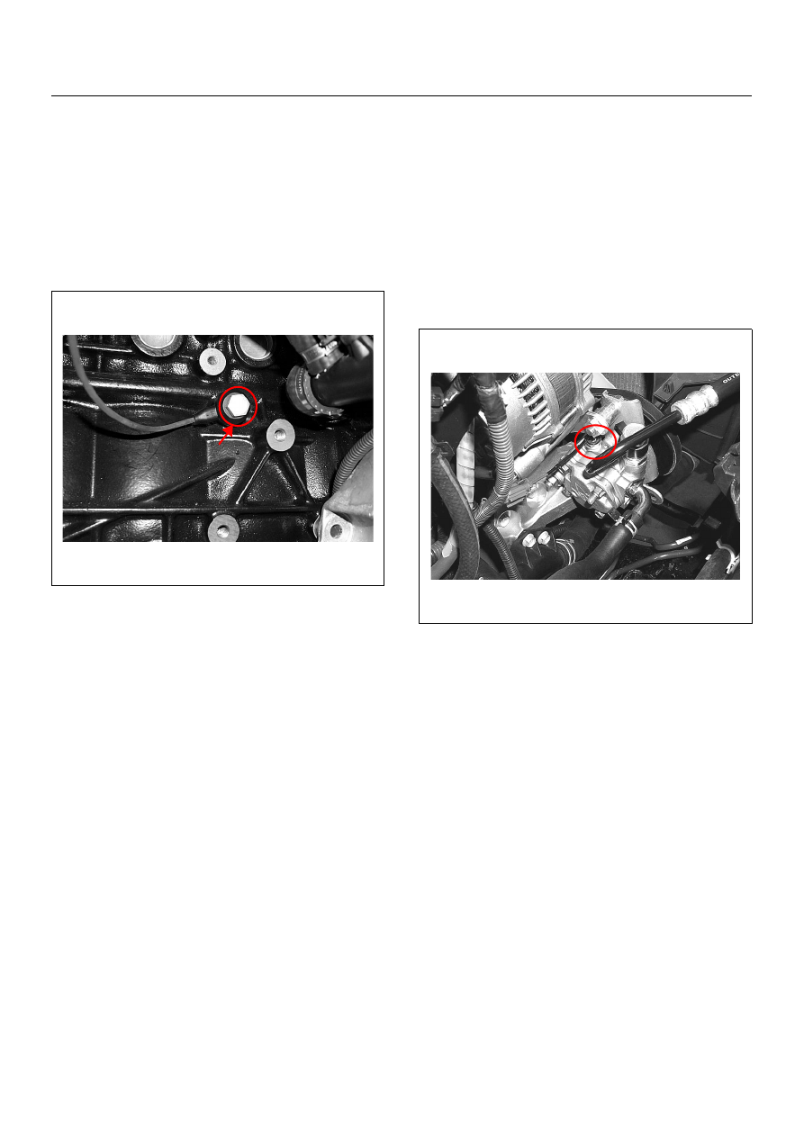
KNOCK SENSOR
Location
Right-hand side of the cylinder block.
Removal Procedure
1. Disconnect the negative battery cable.
2. Disconnect the knock sensor connector.
3. Loosen a bolt and remove knock sensor from the
cylinder block.
Installation Procedure
1. Tighten the knock sensor by a bolt with specified
tightening torque.
Tightening Torque
• Bolt: 20N·m (2.0kgf·m)
2. Connect a knock sensor connector to the knock
sensor.
3. Connect the negative battery cable.
NOTE: Verify any DTCs (diagnosis Trouble Code) are
not stored after replacement.
POWER STEERING PRESSURE
(PSP) SWITCH
Location
Installed on the power steering pump assembly.
Removal Procedure
1. Disconnect the negative battery cable.
2. Disconnect the power steering pressure switch
connector.
3. Loosen and remove the power steering pressure
switch from the power steering pump.
Installation Procedure
1. Install the power steering pressure switch to the
power steering pump.
2. Tighten the power steering pressure switch.
3. Connect a connector to the power steering pressure
switch.
4. Connect the negative battery cable.
NOTE: Verify any DTCs (diagnosis Trouble Code) are
not stored after replacement.
Verify no power steering fluid leaking from the sensor
threads after replacement.

6E–262
ENGINE DRIVEABILITY AND EMISSIONS
HEATED OXYGEN SENSOR (HO2S)
Location
Installed on the exhaust pipe.
Removal Procedure
1. Disconnect the negative battery cable.
2. Disconnect the O
2
sensor connector.
3. Loosen and remove the O
2
sensor from the exhaust
pipe.
Inspection
Inspect the louvered end of the sensor for grease, dirt,
excessive carbon build up or other contamination.
Installation Procedure
1. Install the O
2
sensor to the exhaust pipe.
2. Tighten the O
2
sensor with specified tightening
torque.
Tightening Torque
• Bolt: 42N·m (4.3kgf·m)
3. Connect a O
2
sensor connector to the O
2
sensor.
4. Connect the negative battery cable.
NOTE: Verify any DTCs (diagnosis Trouble Code) are
not stored after replacement.
Verify no exhaust gas leaking from the sensor threads
after replacement.
EVAP CANISTER PURGE VALVE
SOLENOID
Location
On the intake manifold.
Removal Procedure
1. Disconenct the negative battery cable.
2. Disconnect a purge solenoid connector from the
purge solenoid.
3. Disconnect two hoses from the purge solenoid
valve.
4. Slide from the bracket and remove the purge
solenoid.
Installation Procedure
1. Insert EVAP purge solenoid valve onto the bracket.
2. Connect two hoses to the purge solenoid valve.
3. Connect a purge solenoid connector to the purge
solenoid.
4. Connect the negative battery cable.
NOTE: Verify any DTCs (diagnosis Trouble Code) are
not stored after replacement.
Verify proper connection of two hoses.
ENGINE DRIVEABILITY AND EMISSIONS
6E–263
FUEL PRESSURE RELIEF
Caution: To reduce the risk of fire and personal
injury, it is necessary to relieve the fuel system
pressure before servicing the fuel system
components.
Caution: After relieving the fuel system pressure, a
small amount of fuel may be released when
servicing fuel lines or connections. Reduce the
chance of personal injury by covering the fuel line
fitting with a short towel before disconnecting the
fittings. The towel will absorb any fuel that may leak
out. When the disconnect is completed, place the
towel in an approved container.
1. Remove the fuel filler cap.
2. Remove the fuel pump relay from the underhood
relay box.
3. Start the engine and allow it to stall.
4. Crank the engine for about 30 seconds.
5. Disconnect the negative battery cable.
FUEL RAIL ASSEMBLY
Removal Procedure
NOTE:
• Use care when removing the fuel rail assembly in
order to prevent damage to the injector al connector
terminal and the injector spray tips.
• Fitting should be capped and holes plugged during
servicing to prevent dirt and other contaminants from
entering open lines and passage.
Important: An eight-digit identification number is
stamped on side of the fuel injector. Refer to this
number when you service the fuel rail or when a
replacement part is required.
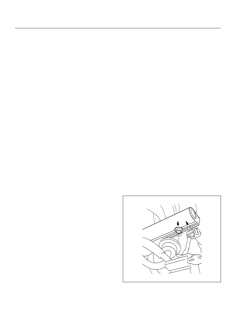
1. Disconnect 4 injector connectors.
2. Lift side-clip up on the fuel rail.
3. Disconnect fuel pressure regulator hose.
4. Disconnect wiring harness from the bands on the
fuel rail.
5. Remove the intake pipe.
6. Loosen flare nut.
A. Lift up the injectors carefully to separate them
from intake manifold.
B. Lift up the fuel rail with injectors as assembly. Do
not separate the fuel injectors from fuel rail.
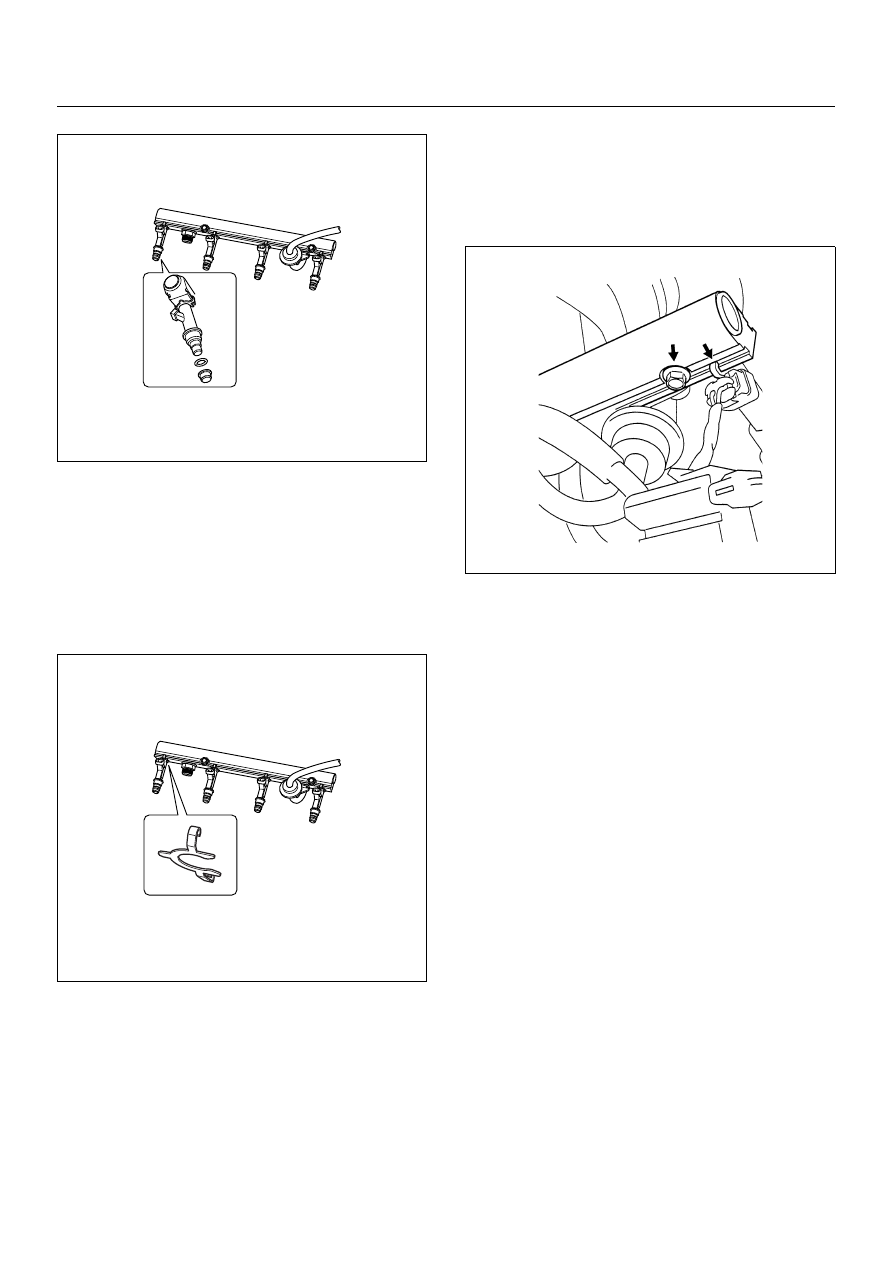
C. If an injector become separated from fuel rail,
injector backup O-ring and injector retainer clip
must be replaced.
D. Drain residual fuel from fuel rail into an
approved container.
7. If removal of fuel pressure regulator is necessary,
Refer to Fuel Pressure Regulator Removal
Procedure.
8. If removal of fuel injector is necessary, Refer to Fuel
Injectors Removal Procedure.
6E–264
ENGINE DRIVEABILITY AND EMISSIONS
Installation Procedure
1. Install the fuel injectors if necessary. Refer to Fuel
Injector Installation Procedure.
2. Install the fuel pressure regulator if necessary. Refer
to Fuel Pressure Regulator Installation Procedure.
3. Place the fuel injector rail assembly on the manifold
and insert the injectors into each port by pushing
fuel rail.
4. Install two fuel rail retaining bolts. Tighten fuel rail
retaining bolt to 19 N·m (1.9kgf·m)
5. Place wiring harness in its place and secure it with
two nuts.
6. Connect all connector to each fuel injector.
7. Connect the fuel supply line securely. Do not over
tighten.
8. Connect the fuel return line securely. Do not over
tighten.
9. Connect the negative battery cable.
10. Crank the engine until it starts. Cranking the engine
may take longer than usual due to trapped air in the
fuel system. Check for leak. If fuel leak is observed,
stop engine immediately. Before correcting fuel
leak, be sure to depressurize system again.
Нет комментариевНе стесняйтесь поделиться с нами вашим ценным мнением.
Текст