Isuzu D-Max / Isuzu Rodeo (TFR/TFS). Manual — part 254
ENGINE DRIVEABILITY AND EMISSIONS
6E–257
ON-VEHICLE SERVICE PROCEDURE
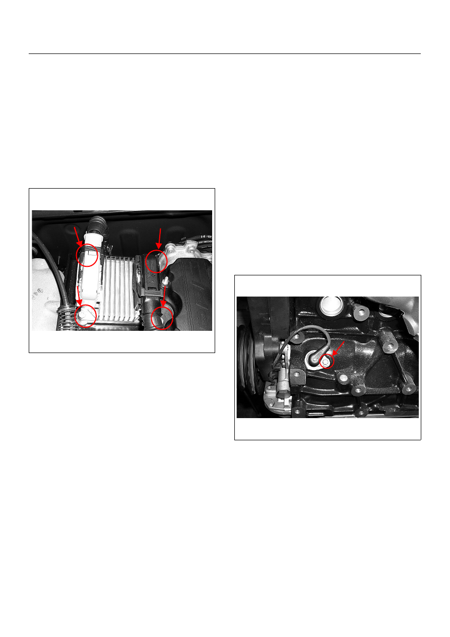
ENGINE CONTROL MODULE (ECM)
Location
On the intake manifold.
Removal Procedure
1. Disconnect the negative battery cable.
2. Disconnect the two connectors from the ECM.
3. Remove four bolts.
4. Remove the ECM from bracket.
Installation Procedure
1. Put on the ECM to the bracket.
2. Tighten the ECM by four bolts with specified
tightening torque.
Tightening torque
• Bolts: 8.0 - 12.0 N·m (0.8 - 1.2 kgf·m)
3. Connect the two connectors to the ECM.
4. Connect the negative battery cable.
NOTE: Verify any DTCs (diagnosis Trouble Code) are
not stored after replacement.
CRANKSHAFT POSITION (CKP)
SENSOR
Location
Left-hand side of the cylinder block. (Back of the A/C
compressor)
Removal Procedure
1. Disconnect the negative battery cable.
2. Remove the drive belt. Refer to Engine Mechanical
Section.
3. Remove the A/C compressor from engine. Refer to
Engine Mechanical Section.
4. Disconnect connector from the CKP sensor.
5. Loosen a bolt and remove the CKP sensor from the
cylinder block.
NOTE: Use caution to avoid any hot oil that might drip
out.
Installation Procedure
1. Install the CKP sensor to the cylinder block.
2. Tighten CKP sensor by a bolt with specified
tightening torque.
Tightening Torque
• Bolt: 6N·m (0.6kgf·m)
3. Reinstall the A/C compressor to the engine.
4. Reinstall the accessory drive belt.
5. Connect the negative battery cable.
NOTE: Verify any DTCs (diagnosis Trouble Code) are
not stored after replacement.
6E–258
ENGINE DRIVEABILITY AND EMISSIONS
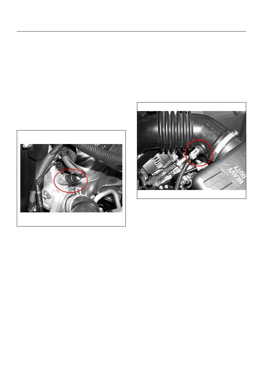
ENGINE COOLANT TEMPERATURE
(ECT) SENSOR
Location
Installed to the thermostat housing.
Removal Procedure
1. Disconnect the negative battery cable.
2. Drain enough engine coolant so that the coolant
level will be below the ECT sensor.
3. Disconnect connector from the ECT sensor.
4. Loosen and remove the ECT sensor from the
thermostat housing.
NOTE: Cool down the engine before above procedures
are carried out.
Installation Procedure
1. Apply sealer to threads of screw at the ECT sensor.
2. Tighten the ECT sensor with specified tightening
torque.
Tightening Torque
• Bolt: 13N·m (1.3kgf·m)
3. Connect a ECT sensor connector to the ECT
sensor.
4. Fill the engine coolant.
5. Connect the negative battery cable.
NOTE: Verify any DTCs (diagnosis Trouble Code) are
not stored after replacement.
Verify no engine coolant leaking from the sensor
threads after replacement.
INTAKE AIR TEMPERATURE (IAT)
SENSOR
Location
Installed to the intake duct housing.
Removal Procedure
1. Disconnect the negative battery cable.
2. Disconnect a IAT sensor connector from the IAT
sensor.
3. Remove the IAT sensor from the intake duct.
Installation Procedure
1. Install the IAT sensor into intake air duct.
2. Connect a IAT sensor connector to the IAT sensor.
3. Connect the negative battery cable.
NOTE: Verify any DTCs (diagnosis Trouble Code) are
not stored after replacement.
ENGINE DRIVEABILITY AND EMISSIONS
6E–259
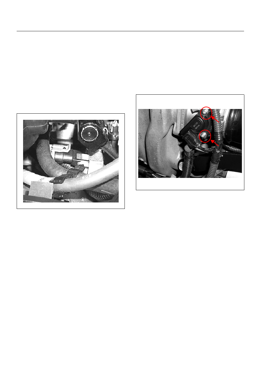
MANIFOLD ABSOLUTE PRESSURE
(MAP) SENSOR
Location
Installed on the intake manifold.
Removal Procedure
1. Disconenct the negative battery cable.
2. Disconnect a MAP sensor connector from the MAP
sensor.
3. Loosen a bolt and remove the MAP sensor from the
intake manifold.
4. Remove the MAP sensor from the bracket.
Installation Procedure
1. Tighten the MAP sensor by a bolt with specified
tightening torque.
Tightening Torque
• Bolt: 8N·m (0.8kgf·m)
2. Connect a MAP sensor connector to the MAP
sensor.
3. Connect the negative battery cable.
NOTE: Verify any DTCs (diagnosis Trouble Code) are
not stored after replacement.
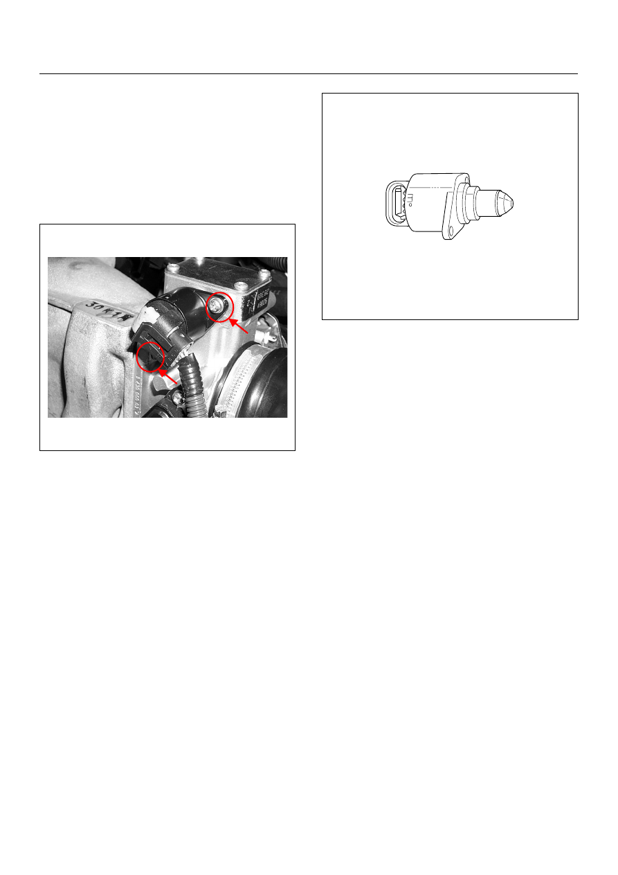
THROTTLE POSITION SENSOR (TPS)
Location
Installed on the throttle body.
Removal Procedure
1. Disconnect the negative battery cable.
2. Disconnect the TPS connector.
3. Loosen two screws and remove TPS from the
throttle body.
Installation Procedure
1. Temporary tighten the TPS by two screws.
2. Connect a TPS connectors to the TPS.
3. Connect the Tech2 to the vehicle.
4. Connect the negative battery cable.
5. Select "Data Display" with the Tech2.
6. Check the throttle position data and adjust the TPS
position.
7. Tighten two screws.
NOTE: Verify any DTCs (diagnosis Trouble Code) are
not stored after replacement.
6E–260
ENGINE DRIVEABILITY AND EMISSIONS
IDLE AIR CONTROL (IAC) VALVE
Location
Installed on the throttle body.
Removal Procedure
1. Disconnect the negative battery cable.
2. Disconnect the IAC valve connector.
3. Loosen two screws and remove IAC valve from the
throttle body.
Cleaning and Inspection
1. Clean the IAC valve O-ring sealing surface, pintle
valve seat and air passage.
2. Use carburetor cleaner and a parts cleaning brush
to remove carbon deposit.
Do not use a cleaner that contain methyl ethyl
ketone. This is an extremely strong solvent and not
necessary for this type of deposit.
3. Shiny spots on the pintle are normal and do not
indicate misalignment or a bent pintle shaft.
4. Inspect the IAC valve O-ring for cuts, cracks or
distortion.
Measurement
• Clean the IAC valve O-ring sealing surface, pintle
valve seat and air passage.
• Use carburetor cleaner and a parts cleaning brush to
remove carbon deposit. Do not use a cleaner that
contain methyl ethyl ketone. This is an extremely
strong solvent and not necessary for this type of
deposit.
• Shiny spots on the pintle are normal and do not
indicate misalignment or a bent pintle shaft.
• Inspect the IAC valve O-ring for cuts, cracks or
distortion. Replace the O-ring if damaged.
Installation Procedure
1. Tighten the IAC valve by two screws.
2. Connect a IAC valve connector to the MAP sensor.
3. Connect the negative battery cable.
NOTE: Verify any DTCs (diagnosis Trouble Code) are
not stored after replacement.
Нет комментариевНе стесняйтесь поделиться с нами вашим ценным мнением.
Текст