Isuzu D-Max / Isuzu Rodeo (TFR/TFS). Manual — part 549
6A – 34 ENGINE MECHANICAL
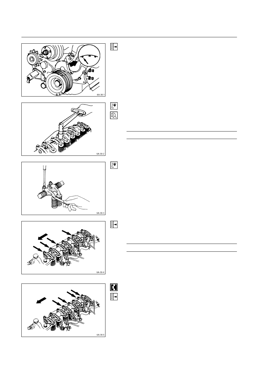
VALVE CLEARANCE ADJUSTMENT
1. Bring the piston in either the No. 1 cylinder or the No. 4
cylinder to TDC on the compression stroke by turning
the crankshaft until the crankshaft damper pulley TDC
line is aligned with the timing pointer.
2. Check the rocker arm shaft bracket nuts for
looseness.
Tighten any loose rocker arm shaft bracket nuts
before adjusting the valve clearance.
Rocker Arm Shaft Bracket Nut Torque
kg·m (lb·ft/N·m)
5.5
± 0.5 (39.8 ± 3.6/53.9 ± 4.9)
3. Check for play in the No. 1 intake and exhaust valve
push rods.
If the No. 1 cylinder intake and exhaust valve push
rods have play, the No. 1 piston is at TDC on the
compression stroke.
If the No. 1 cylinder intake and exhaust valve push
rods are depressed, the No. 4 piston is at TDC on the
compression stroke.
Adjust the No.1 or the No. 4 cylinder valve clearances
while their respective cylinders are at TDC on the
compression stroke.
Valve Clearance (At Cold)
mm (in)
0.4 (0.016)
4. Loosen each valve clearance adjusting screw as
shown in the illustration.
5. Insert a feeler gauge of the appropriate thickness
between the rocker arm and the valve stem end.
6. Turn the valve clearance adjusting screw until a slight
drag can be felt on the feeler gauge.
7. Tighten the lock nut securely.
8. Rotate the crankshaft 360
°.
9. Realign the crankshaft damper pulley TDC notched
line with the timing pointer.
10 Adjust the clearances for the remaining valves as
shown in the illustration.
ENGINE MECHANICAL 6A – 35
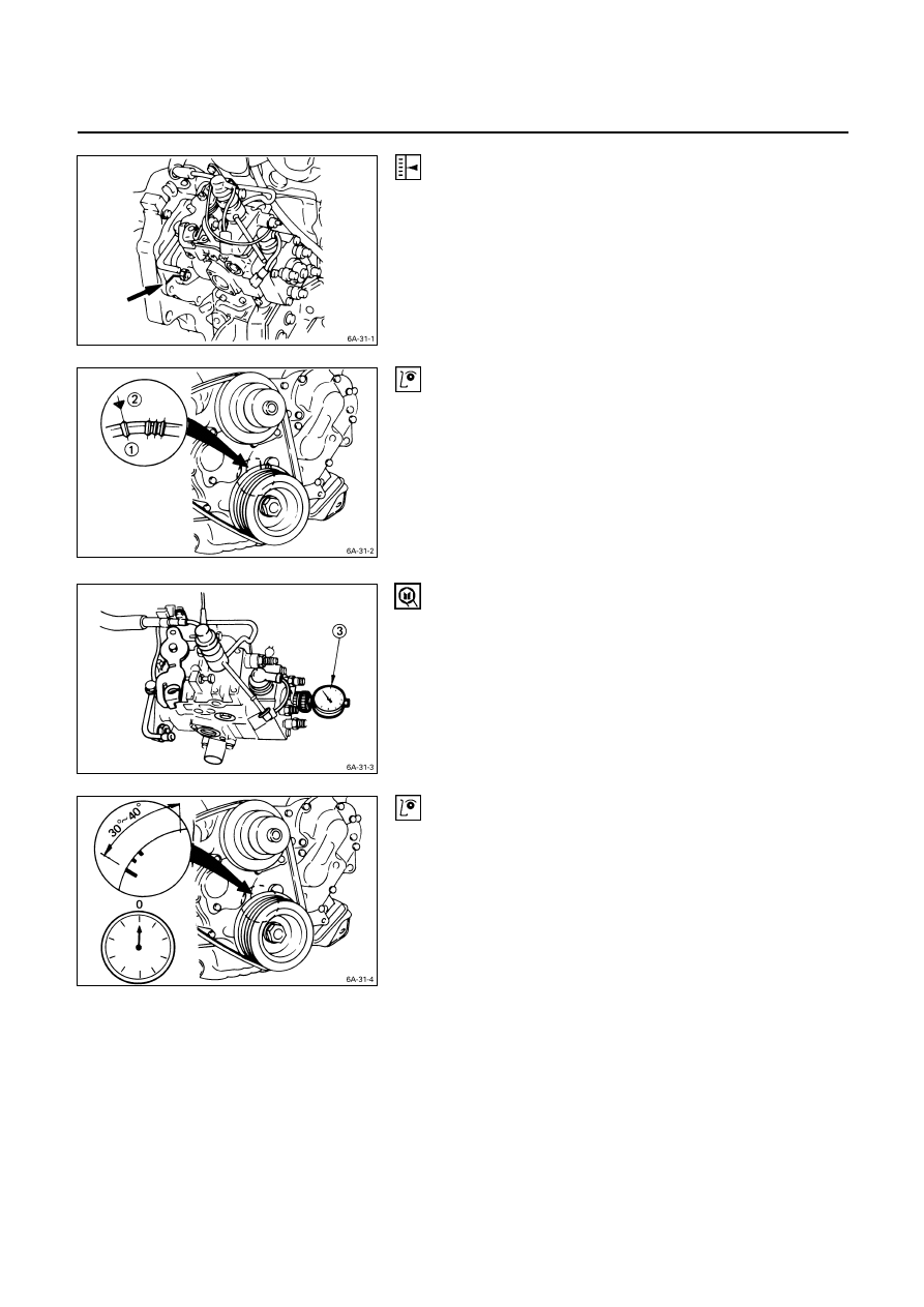
INJECTION TIMING ADJUSTMENT
(Except 4JA1TC, 4JH1TC)
1. Check that the notched line on the injection pump
flange is aligned with the front plate or the timing gear
case notched line.
2. Bring the piston in the No. 1 cylinder to TDC
Q
on the
compression stroke by turning the crankshaft until the
crankshaft pulley TDC line is aligned with the timing
mark
R
.
Note:
Check for play in the No. 1 intake and exhaust valve
push rods.
If the No. 1 cylinder intake and exhaust valve push
rods have play, the No. 1 piston is at TDC on the
compression stroke.
3. Disconnect the injection pipe from the injection pump
4. Remove one bolt from the distributor head.
5. Insert a screwdriver into a hole in the fast idle lever
and turn the lever to release the W-C.S.D. function. (if
so equipped)
6. Install the static timing gauge
S
.
The probe of the gauge should be depressed inward
approximately 2 mm (0.079 in).
Static Timing Gauge: 5-8840-0145-0 (J-28827)
7. Rotate the crankshaft to bring the piston in the No. 1
cylinder to a point 30 - 40
° BTDC.
8. Set the timing gauge needle to zero.
9. Move the crankshaft pulley slightly in both directions to
check that the gauge indication is stable.

6A – 36 ENGINE MECHANICAL
10. Turn the crankshaft clockwise and read the gauge
indication when the crankshaft pulley timing mark (12
°
(4JA1, 4JA1T) 11
° (4JB1T) 0° (4JG2T) on pulley) is
aligned with the pointer.
4JA1 4JA1T 4JB1T 4JG2T
BTDC
12
± 2°
BTDC
12
± 2°
BTDC
11
± 2°
TDC
0
± 2°
Standard Reading
mm (in)
0.5 (0.02)
If the injection timing is outside the specified range,
continue with the following steps.
11. Loosen the injection pump fixing nuts and bracket
bolts.
12. Adjust the injection pump setting angle.
When
large
than
standard value
When smaller than
standard value
Gear drive
R
A
A: Move the injection pump toward the engine.
R: Move the injection pump away from the engine.
COMPRESSION PRESSURE
MEASUREMENT
1. Start the engine and allow it to idle until the coolant
temperature reaches 70 – 80
°C (158 – 176 °F).
2. Remove the following parts.
• Glow
plugs
• Fuel cut solenoid connector
3. Set the adapter and compression gauge to the No. 1
cylinder glow plug hole.
Compression Gauge: 5-8840-2675-0
Adapter; Compression Gauge: 5-8531-7001-0
4. Turn the engine over with the starter motor and take
the compression gauge reading.
Compression Pressure
kg/cm
2
(psi/MPa) at 200 rpm
Standard
Limit
4JH1TC
28 (398/2.8)
20 (284/2.0)
Others
31 (441/3.0)
22 (313/2.2)
5. Repeat the procedure (Steps 3 and 4) for the
remaining cylinders.
If the measured value is less than the specified limit,
refer to “Troubleshooting” in this Manual.
ENGINE MECHANICAL 6A – 37
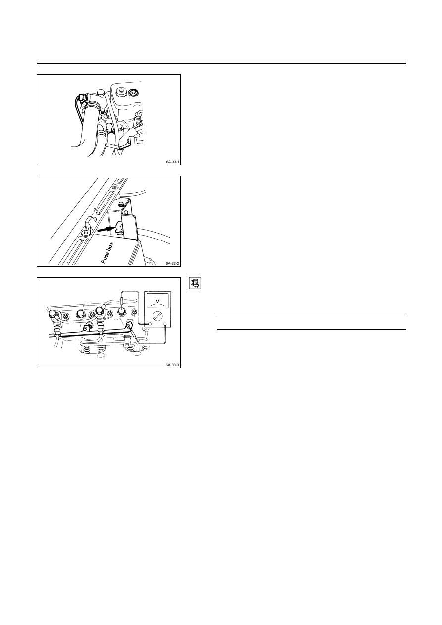
PRE-HEATING SYSTEM
System Inspection Procedure
1. Disconnect the thermo-switch on the thermostat outlet
pipe.
2. Turn the starter switch to the “ON” position.
If the Pre-heating System is operating properly, the
glow relay will make a clicking sound about seven
seconds after the starter switch is turned on.
3. Measure the glow plug terminal voltage with a circuit
tester immediately after turning the starter switch to
the “ON” position.
Glow Plug Terminal Voltage
V
Approx. 11
Нет комментариевНе стесняйтесь поделиться с нами вашим ценным мнением.
Текст