Isuzu D-Max / Isuzu Rodeo (TFR/TFS). Manual — part 548

6A – 30 ENGINE MECHANICAL
Thermostat Operating Test
1. Completely submerge the thermostat in water.
2. Heat
the
water.
Stir the water constantly to avoid direct heat being
applied to the thermostat.
3. Check the thermostat initial opening temperature.
Thermostat Initial Opening Temperature
°C (°F)
82 (180)
4. Check the thermostat full opening temperature.
Thermostat Full Opening Temperature
°C (°F)
95 (203)
Valve Lift at Fully Open position
mm (in)
9.5 (0.37)
Q
Thermometer
R
Agitating rod
S
Wooden piece
ENGINE MECHANICAL 6A – 31
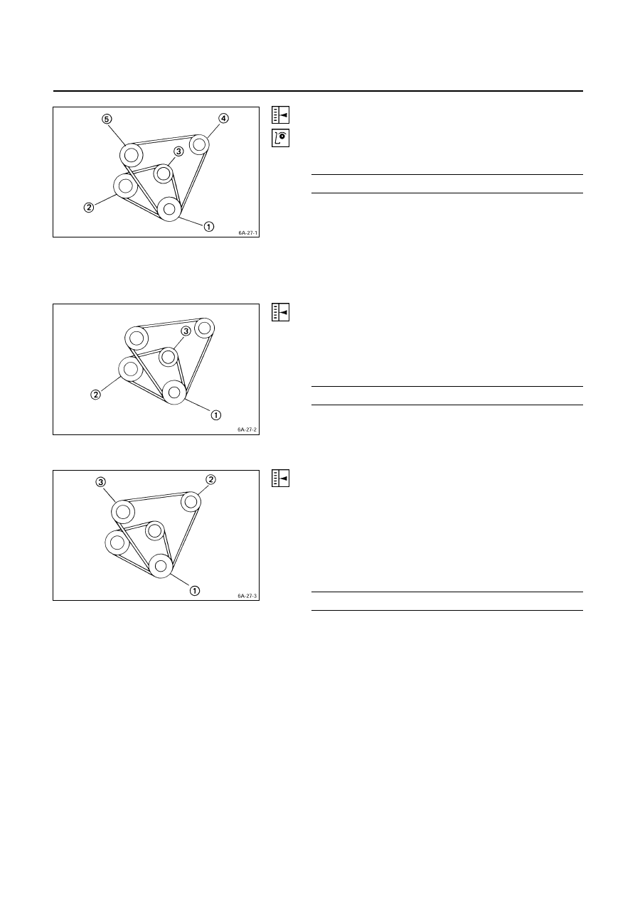
Drive Belt Adjustment
Depress the drive belt mid-portion with a 10 kg (22 lb/98N)
force.
Drive Belt Deflection
mm (in)
10 (0.39)
Check the drive belt for cracking and other damage.
Q
Crankshaft damper pulley
R
Generator pulley
S
Cooling fan pulley
T
Oil pump pulley or idler pulley
U
Compressor pulley or idler pulley
Cooling Fan Pulley Drive Belt
Fan belt tension is adjusted by moving the generator.
Depress the drive belt mid-portion with a 10 kg (22 lb/98N)
force.
Drive Belt Deflection
mm (in)
10 (0.39)
Q
Crankshaft damper pulley
R
Generator pulley
S
Cooling
fan pulley
Compressor Pulley Drive Belt
Move the idler pulley as required to adjust the compressor
drive belt tension.
If the vehicle is equipped with power steering, move the oil
pump as required
Depress the drive belt mid-portion with a 10 kg (22 lb/98
N) force.
Belt Deflection
mm (in)
12 – 15 (0.47 – 0.59)
Q
Crankshaft damper pulley
R
Oil pump pulley or idler pulley

6A – 32 ENGINE MECHANICAL
Power Steering Oil Pump Pulley Drive Belt
Move the oil pump as required to adjust the oil pump drive
belt tension.
On air conditioner equipped models, both drive belts pulley
must always be replaced as a set.
Depress the drive belt mid-portion with a 10 kg (22 lb/98
N) force.
Belt Deflection
mm (in)
14 - 17 (0.55 – 0.67)
Q
Crankshaft damper pulley
R
Oil pump pulley
S
Compressor pulley or idler pulley
ENGINE CONTROL
Idling Speed Adjustment
1. Set the vehicle parking brake and chock the drive
wheels.
2. Place the transmission in neutral.
3. Start the engine and allow it to idle until the coolant
temperature reaches 70 - 80
°C (158 - 176°F).
4. Disconnect the engine control cable from the control
lever.
5. Set a tachometer to the engine.
6. Check the engine idling speed.
If the engine idling speed is outside the specified
range, it must be adjusted.
Engine Idling Speed
rpm
4JA1, 4JB1
750
± 50
4JA1T
770
± 50
4JG2T
720
± 50
4JA1TC
730
± 25
4JH1TC
700
± 25
Idling Speed Adjustment
(Except 4JA1TC, 4JH1TC)
1. Loosen the idling set screw lock nut
Q
on the injection
pump idling set bolt.
2. Adjust the idling speed to the specified range by
turning the idling set bolt
R
.
3. Lock the engine set nut
Q
with the idling set bolt lock
nut.
4. Check that the idling control cable is tight (free of
slack). If required, remove the slack from the cable.

ENGINE MECHANICAL 6A – 33
Fast Idling Speed Inspection
1. Set tachometer to the engine.
2. Disconnect the vacuum hose
Q
from the fast idle
actuator
U
on the injection pump.
3. Disconnect the other vacuum hose
R
from the
vacuum switching valve
S
and connect it to the fast
idle actuator
U
.
The vacuum line will now be connected directly from
the vacuum pump
T
to the fast idle actuator.
4. Check the engine fast idling speed.
If the engine idling speed is outside the specified
range, it must be adjusted.
Fast Idling Speed
rpm
850 - 950
Fast Idling Speed Adjustment
1. Loosen the fast idle actuator bracket bolts.
1. Adjust the fast idling speed by moving the actuator
bracket, so that the clearance “S” can be 1 ~ 2 mm
(0.04 ~ 0.08 in.).
2. Tighten the bracket bolts.
Accelerator Control
Accelerator Control Cable Adjustment
1. Loosen the accelerator cable clamp bolt
Q
.
2. Check that the idling control knob is in the engine
idling position.
3. Hold the accelerator lever
R
in the fully closed
position and stretch the control cable
S
in the
direction indicated by the arrow to remove any slack.
101RY00014
Нет комментариевНе стесняйтесь поделиться с нами вашим ценным мнением.
Текст