Isuzu D-Max / Isuzu Rodeo (TFR/TFS). Manual — part 30
4JA1-TC/4JH1-TC ENGINE DRIVEABILITY AND EMISSIONS
6E–115
8
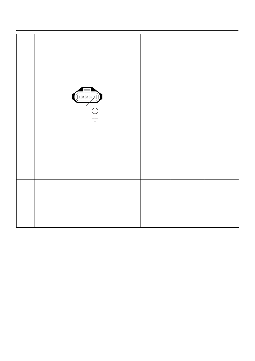
Using the DVM and check the MAF sensor signal
circuit.
1. Ignition “On”, engine “Off”.
2. Disconnect the MAF sensor connector.
3. Check the circuit for short to power supply circuit.
Was the DVM indicated specified value?
Less than 1V
Go to Step 9
Repair faulty
harness and
verify repair
9
Substitute a known good MAF & IAT sensor assembly
and recheck.
Was the problem solved?
—
Go to Step 10
Go to Step 11
10
Replace the MAF & IAT sensor assembly.
Is the action complete?
—
Verify repair
—
11
Is the ECM programmed with the latest software
release?
If not, download the latest software to the ECM using
the “SPS (Service Programming System)”.
Was the problem solved?
—
Verify repair
Go to Step 12
12
Replace the ECM.
Is the action complete?
IMPORTANT: The replacement ECM must be
programmed. Refer to section of the Service
Programming System (SPS) in this manual.
Following ECM programming, the immobiliser system
(if equipped) must be linked to the ECM. Refer to
section 11 “Immobiliser System-ECM replacement” for
the ECM/Immobiliser linking procedure.
—
Verify repair
—
Step
Action
Value(s)
Yes
No
5
V
C-51

6E–116
4JA1-TC/4JH1-TC ENGINE DRIVEABILITY AND EMISSIONS
DIAGNOSTIC TROUBLE CODE (DTC) P0110 (SYMPTOM CODE 1)
(FLASH CODE 23) INTAKE AIR TEMPERATURE (IAT) SENSOR CIRCUIT HIGH
INPUT
DIAGNOSTIC TROUBLE CODE (DTC) P0110 (SYMPTOM CODE 2)
(FLASH CODE 23) INTAKE AIR TEMPERATURE (IAT) SENSOR CIRCUIT LOW
INPUT
Condition for setting the DTC and action taken when the DTC sets
Circuit Description
The IAT sensor is a thermistor. A temperature changes
the resistance value. And it changes voltage. In other
words it measures a temperature value. Low air
temperature produces a high resistance.
Flash
Code
Code
Symptom
Code
MIL
DTC Name
DTC Setting Condition
Fail-Safe (Back Up)
23
P0110
1
ON
Intake Air Temperature (IAT)
Sensor Circuit High Input
IAT sensor output voltage is
more than 4.7V.
ECM use 0°C conditions as
substitute.
2
ON
Intake Air Temperature (IAT)
Sensor Circuit Low Input
IAT sensor output voltage is
below 0.3V.
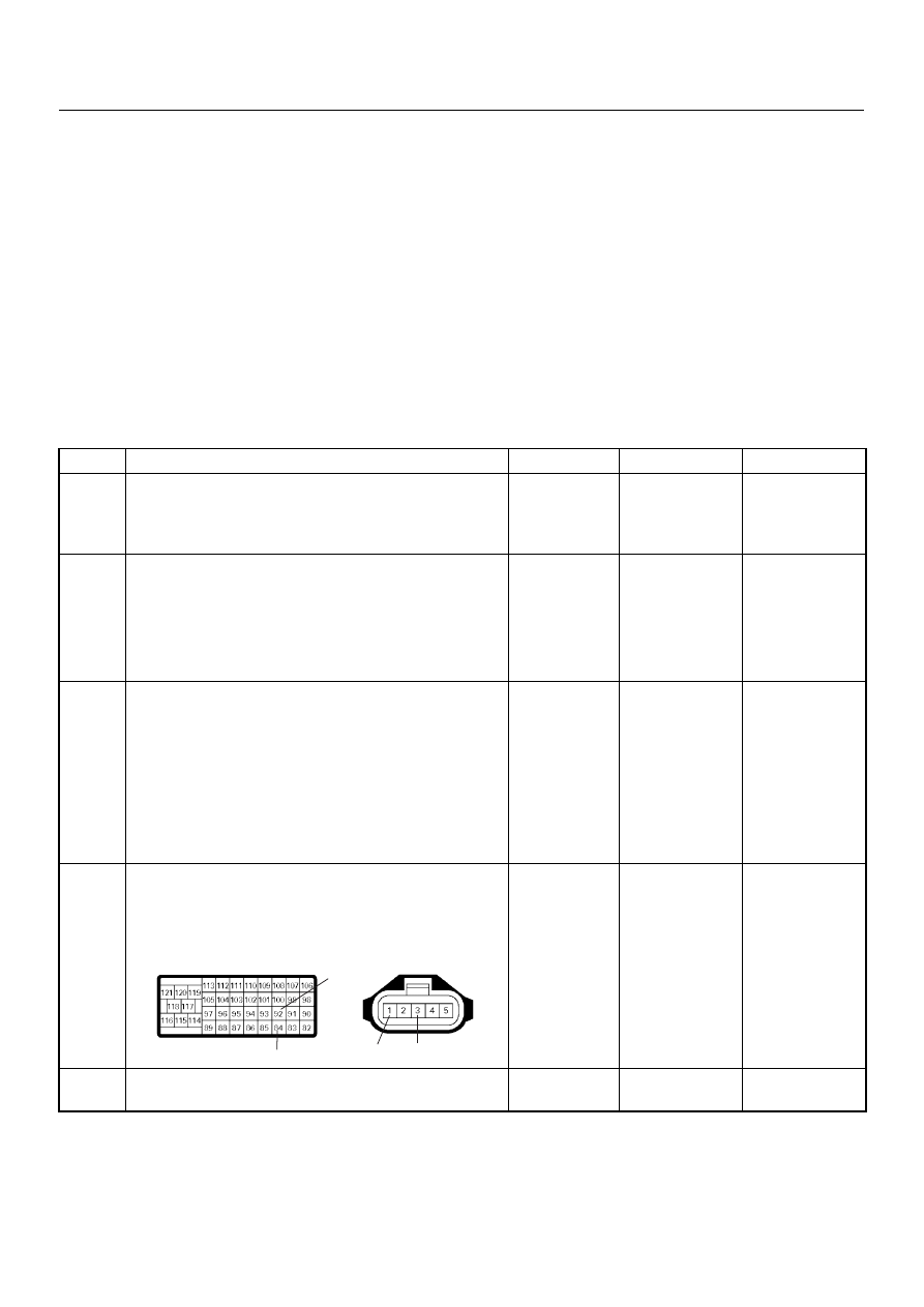
Batt
µP
Batt
µP
Batt
µP
0.5
BLK/
URG
0.5
BRN/
RED
0.5
BLU/
RED
0.5
BLU/
RED
4JA1-TC
0.5
GRY/
YEL
97
46
61
0.5
WHT/
RED
83
0.5
GRN/
RED
88
0.5
BLK/
RED
92
0.5
BLK/
BLU
84
IAT
Sensor
MAF &
IAT
Sensor
Rr Fog
Light
10A
EGR-
EVRV
0.5
WHT/
BLK
0.5
BLU/
RED
0.5
WHT/
BLU
0.5
BLU/
RED
0.5
GRN/
RED
0.5
BLU/
RED
Exhaust
Throttle
VSV2
Exhaust
Throttle
VSV1
Engine
Warming Up
SW
Thermo
SW
2
4
5
3
1
Battery
Voltage
ECM
Main Relay
IC
IC
IC
CPU
Engine
Control
Module
(ECM)
40
4JA1-TC/4JH1-TC ENGINE DRIVEABILITY AND EMISSIONS
6E–117
The ECM supplies 5 volts signal to the IAT sensor
through resisters in the ECM and measures the voltage.
The signal voltage will be high when the air temperature
is cold, and it will be low when the air temperature is hot.
The output voltage excessively high or low, DTC P0110
(Symptom Code 1) or P0110 (Symptom Code 2) will be
stored.
Diagnostic Aids
An intermittent may be caused by the following:
• Poor connections.
• Misrouted harness.
• Rubbed through wire insulation.
• Broken wire inside the insulation.
Check for the following conditions:
• Poor connection at ECM-Inspect harness connectors
for backed out terminals, improper mating, broken
locks, improperly formed or damaged terminals, and
poor terminal to wire connection.
• Damaged harness-Inspect the wiring harness for
damage. If the harness appears to be OK, observe
the “Intake Air Temperature” display on the Tech2
while moving connectors and wiring harness related
to the sensor.
Diagnostic Trouble Code (DTC) P0110 (Symptom Code 1) (Flash Code 23)
Intake Air Temperature (IAT) Sensor Circuit High Input
Step
Action
Value(s)
Yes
No
1
Was the “On-Board Diagnostic (OBD) System Check”
performed?
—
Go to Step 2
Go to On Board
Diagnostic
(OBD) System
Check
2
1. Connect the Tech 2.
2. Review and record the failure information.
3. Select “F0: Read DTC Infor As Stored By ECU” in
“F0: Diagnostic Trouble Codes”.
Is the DTC P0110 (Symptom Code 1) stored as
“Present Failure”?
—
Go to Step 3
Refer to
Diagnostic Aids
and Go to Step
3
3
1. Using the Tech 2, ignition “On” and engine “Off”.
2. Select “F1: Clear DTC Information” in “F0:
Diagnostic Trouble Codes” with the Tech 2 and
clear the DTC information.
3. Operate the vehicle and monitor the “F0: Read
DTC Infor As Stored By ECU” in the “F0:
Diagnostic Trouble Codes”.
Was the DTC P0110 (Symptom Code 1) stored in this
ignition cycle?
—
Go to Step 4
Refer to
Diagnostic Aids
and Go to Step
4
4
Check for poor/faulty connection at the IAT sensor or
ECM connector. If a poor/faulty connection is found,
repair as necessary.
Was the problem found?
—
Verify repair
Go to Step 5
5
Visually check the IAT sensor.
Was the problem found?
—
Go to Step 12
Go to Step 6
92
84
1
3
C-51
C-57(B)
6E–118
4JA1-TC/4JH1-TC ENGINE DRIVEABILITY AND EMISSIONS
6
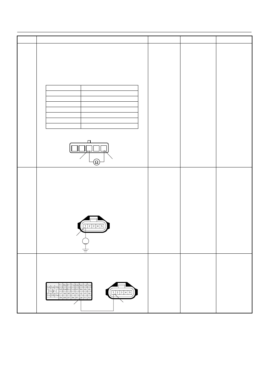
Using the DVM and check the IAT sensor.
1. Ignition “Off”, engine “Off”.
2. Disconnect MAF & IAT sensor connector.
3. Measure the resistance of IAT sensor.
Does the tester indicate standard resistance as shown
in the following table?
Standard
resistance
Go to Step 7
Go to Step 12
7
Using the DVM and check the IAT sensor signal
circuit.
1. Ignition “On”, engine “Off”.
2. Disconnect the MAF & IAT sensor connector.
3. Check the circuit for open circuit.
Was the DVM indicated specified value?
Approximately
5.0V
Go to Step 10
Less than 1V:
Go to Step 8
More than
specified value:
Go to Step 9
8
Repair the open circuit between the ECM and IAT
sensor.
Was the problem solved?
—
Verify repair
Go to Step 14
Step
Action
Value(s)
Yes
No
Temperature (°C)
Resistance (
Ω) (Approximately)
-20
14210
0
5402
20
2343
40
1131
60
596
80
338
100
203
1
2
3
5
4
1
3
IAT Sensor
1
V
C-51
1
84
C-51
C-57(B)
Нет комментариевНе стесняйтесь поделиться с нами вашим ценным мнением.
Текст