Isuzu D-Max / Isuzu Rodeo (TFR/TFS). Manual — part 590

FUEL SYSTEM 6C – 19
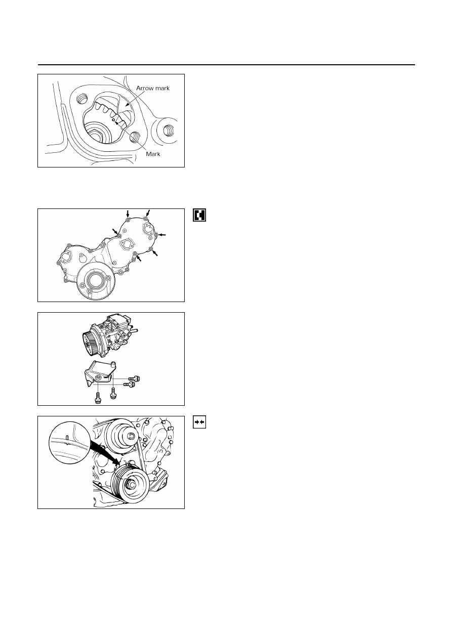
• Install injection pump so that the timing “O” mark on
the pump gear the arrow mark on the timing gear case
cover.
6C – 20 FUEL SYSTEM
GEAR DRIVE MODEL (4JA1TC, 4JH1TC)
Removal Steps
1. Disconnect the battery ground cable.
2. Remove
the
intercooler.
3. Separate the air cleaner duct from the air cleaner.
4. Disconnect the radiator upper hose.
5. Remove the air conditioner V-belt.
6. Remove the power steering V-belt.
7. Remove the power steering oil tank. Place the tank in
a safe place.
8. Remove the fuel filter and its bracket.
9. Disconnect the accelerator cable and connector at the
intake duct.
10. Remove the intake duct.
11. Remove the accelerator control lever.
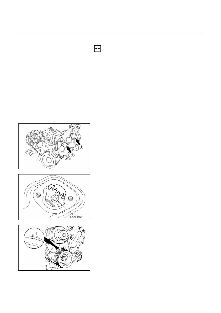
12. Remove the check hole cover from the timing gear
case.
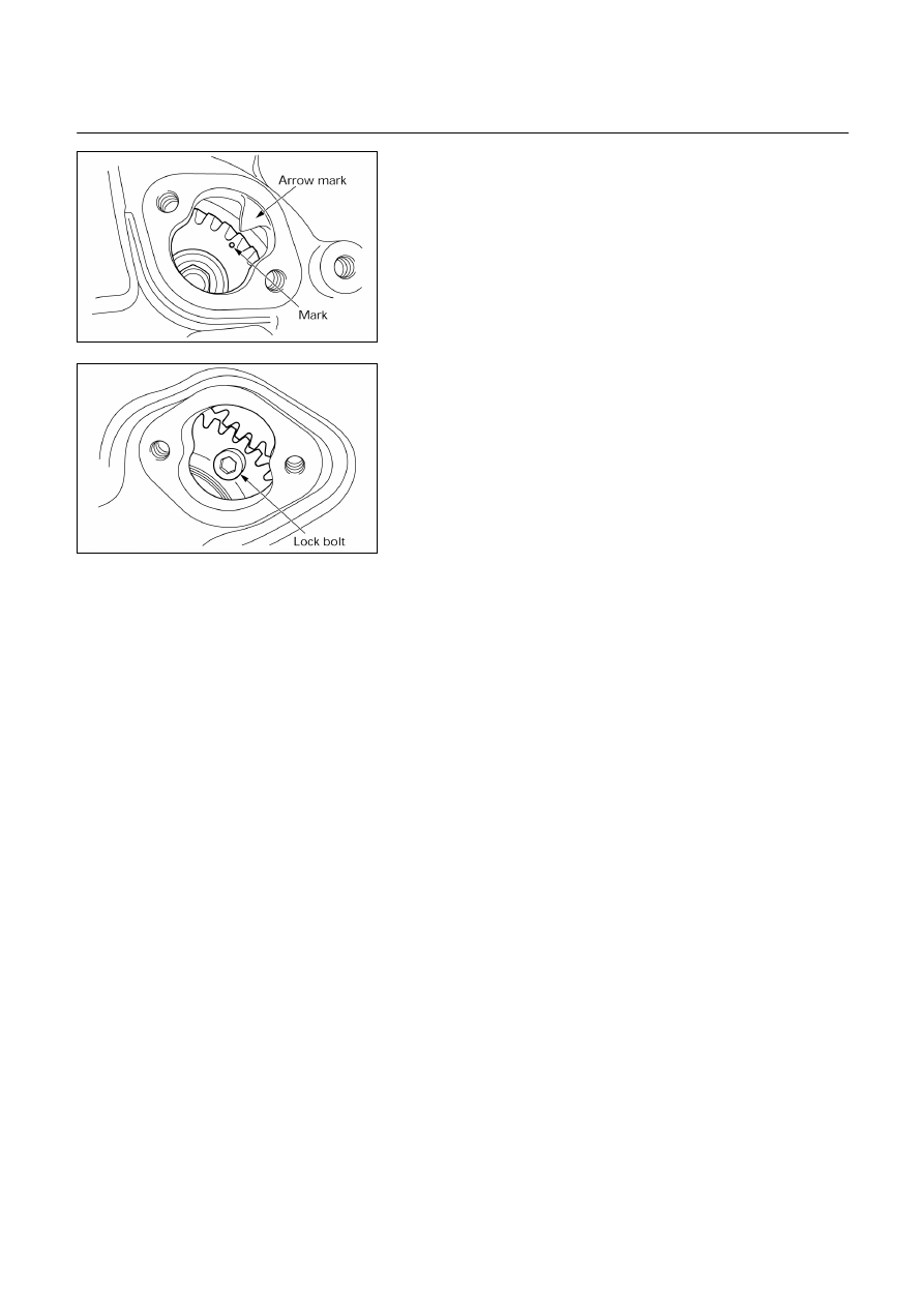
13. Rotate the crank pulley until the scissor gear fixing
hole becomes visible through the check hole (2).
14. Insert a lock bolt (M6×1 L=30) into the scissor gear
fixing hole to prevent the scissor gear from turning.
Note:
If the check hole cover is reinstalled with the lock bolt
still in place, the crank pulley will not turn.
15. Rotate the crank pulley to align the crank pulley TDC
mark and the timing gear case TDC mark.
16. Look through check hole (1) to confirm that the
injection pump alignment mark is visible. If it is not
visible, turn the crank pulley an additional full turn.
020L200016
020L200018
015L200004
FUEL SYSTEM 6C – 21
17. Remove the fuel piping and the injection pipes.
18. Remove the connector from the injection pump.
19. Remove the injection pump mounting bolts (6 bolts)
from the timing gear case.
20. Remove the injection pump bracket.
21. Remove the injection pump and pump gear by pulling
it toward the rear of the engine.
Installation Steps
Follow the removal procedure in reverse order.
Pay close attention to the following.
• Be sure to align the crank pulley TDC mark and the
timing gear case TDC mark.
020L200017
080L200006
015L200004
6C – 22 FUEL SYSTEM
• Install the injection pump and pump gear so that the
timing mark (dot) on the pump gear is aligned with the
arrow on the timing gear case cover.
Note:
•
Do not forget to remove the lock bolt from the
scissor gear. (if you have forgotten to remove the
bolt, the bolt will strike the check hole guides and
the crank pulley will not turn)
•
Injection pump Air bleeding is required to start
the engine when the injection pump has been
replaced.
Refer to Injection Pump Air Bleeding (Section 00).
020L200017
020L200018
Нет комментариевНе стесняйтесь поделиться с нами вашим ценным мнением.
Текст