Isuzu D-Max / Isuzu Rodeo (TFR/TFS). Manual — part 119
6E–80
4JH1 ENGINE DRIVEABILITY AND EMISSIONS
No Check Engine Lamp (MIL)
Step
Action
Value(s)
Yes
No
1
Check the meter fuse (15A).
If the fuse is burnt out, repair as necessary.
Was the problem found?
—
Verify repair
Go to Step 2
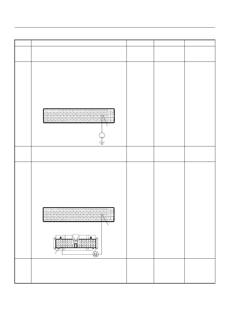
2
Using the DVM and check the “CHECK ENGINE”
lamp circuit.
1. Ignition “Off”, engine “Off”.
2. Disconnect the ECM connector.
3. Ignition “On”.
4. Check the circuit for open circuit.
Was the DVM indicated specified value?
Battery
voltage
Go to Step 5
Go to Step 3
3
Check the “CHECK ENGINE” lamp bulb.
If the bulb is burnt out, repair as necessary.
Was the problem found?
—
Verify repair
Go to Step 4
4
Using the DVM and check the “CHECK ENGINE”
lamp circuit.
1. Ignition “Off”, engine “Off”.
2. Disconnect the meter connector and ECM
connector.
3. Check the circuit for open circuit.
Was the problem found?
—
Verify repair
Go to Step 5
5
Is the ECM programmed with the latest software
release?
If not, download the latest software to the ECM using
the “SPS (Service Programming System)”.
Was the problem solved?
—
Verify repair
Go to Step 6
V
42
C-56
42
17
B-24
C-56

4JH1 ENGINE DRIVEABILITY AND EMISSIONS
6E–81
6
Replace the ECM.
Is the action complete?
IMPORTANT: The replacement ECM must be
programmed. Refer to section of the Service
Programming System (SPS) in this manual.
Following ECM programming, the immobiliser system
(if equipped) must be linked to the ECM. Refer to
section 11 “Immobiliser System-ECM replacement” for
the ECM/Immobiliser linking procedure.
—
Verify repair
—
Step
Action
Value(s)
Yes
No
6E–82
4JH1 ENGINE DRIVEABILITY AND EMISSIONS
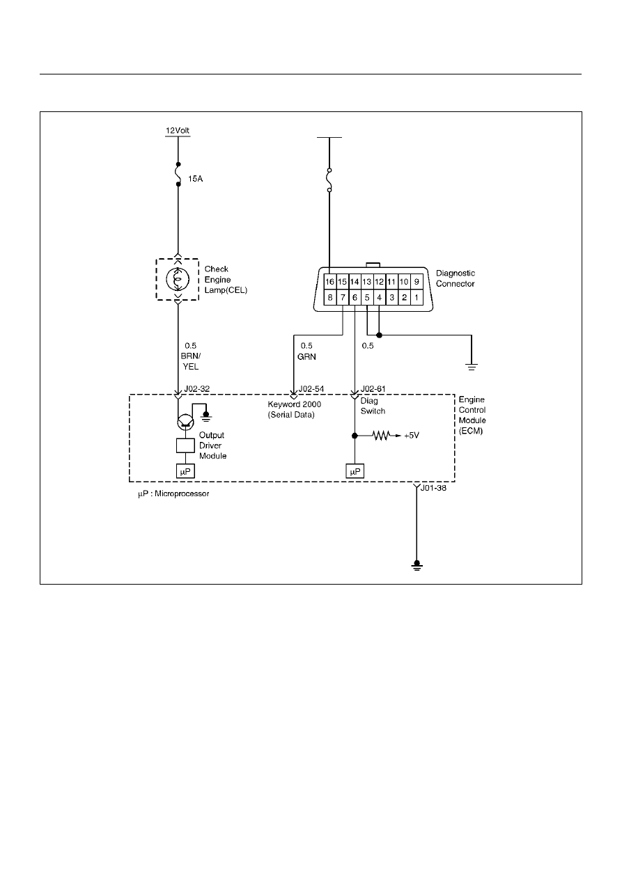
CHECK ENGINE LAMP (MIL) “ON” STEADY
Circuit description
The check engine lamp should always be illuminated
and steady for about five seconds with ignition “ON” and
the engine stopped. Ignition feed voltage is supplied
directly to the check engine lamp indicator. The Engine
Control Module (ECM) turns the check engine lamp
“ON” by grounding the check engine lamp driver circuit.
The check engine lamp should not remain “ON” with the
engine running and no DTC(s) set. A steady check
engine lamp with the engine running and no DTC(s)
suggests a short to ground in the check engine lamp
driver circuit.
Diagnostic Aids
An intermittent may be caused by a poor connection,
rubbed-through wire insulation, or a wire broken inside
the insulation. Check for the following items:
• Poor connection or damaged harness – Inspect the
ECM harness and connectors for improper mating,
broken locks, improperly formed or damaged
terminals, poor terminal-to-wire connection, and
damaged harness.
0.5
BLK
BLK/
GRN
METER (C10)
METER
10A
12Volt
RED/
YEL
(C19)

4JH1 ENGINE DRIVEABILITY AND EMISSIONS
6E–83
Check Engine Lamp (MIL) On Steady
Step
Action
Value(s)
Yes
No
1
1. Ignition “Off”, engine “Off”.
2. Disconnect the ECM connector.
3. Ignition “On”.
Was the “CHECK ENGINE” lamp turned on?
—
Go to Step 2
Go to Step 4
2
Using the DVM and check the “CHECK ENGINE”
lamp circuit.
1. Ignition “Off”, engine “Off”.
2. Disconnect the meter connector and ECM
connector.
3. Check the circuit for short to ground circuit.
Was the problem found?
—
Verify repair
Go to Step 3
3
Replace the meter assembly.
Is the action complete?
—
Verify repair
—
4
Is the ECM programmed with the latest software
release?
If not, download the latest software to the ECM using
the “SPS (Service Programming System)”.
Was the problem solved?
—
Verify repair
Go to Step 5
5
Replace the ECM.
Is the action complete?
IMPORTANT: The replacement ECM must be
programmed. Refer to section of the Service
Programming System (SPS) in this manual.
Following ECM programming, the immobiliser system
(if equipped) must be linked to the ECM. Refer to
section 11 “Immobiliser System-ECM replacement” for
the ECM/Immobiliser linking procedure.
—
Verify repair
—
42
17
B-24
C-56
Нет комментариевНе стесняйтесь поделиться с нами вашим ценным мнением.
Текст