Isuzu D-Max / Isuzu Rodeo (TFR/TFS). Manual — part 300
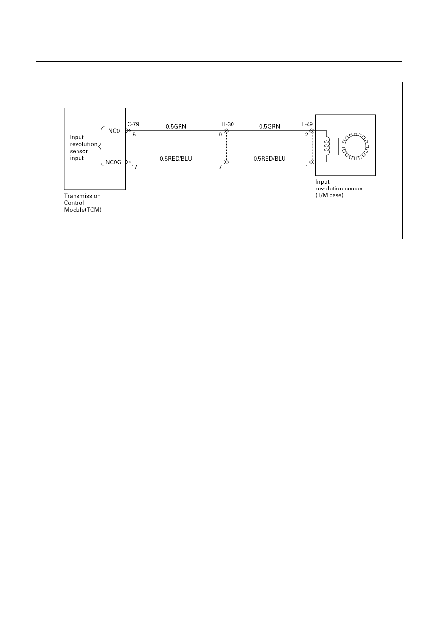
AUTOMATIC TRANSMISSION (AW30-40LE) 7A-49
‘01TFR (For Thailand)
D07L100007
Circuit description:
Input revolution information is provided to TCM by the
input revolution sensor. This sensor is located in the
transmission case.
The input revolution sensor is an electromagnetic pulse
pickup type that generates a speed signal according to
the revolution of the transmission OD direct clutch
drum.
As a result, the sensor sends a sine wave signal (AC)
to the TCM, which converts this sine wave signal (pulse
voltage) to a RPM signal.
Fail-safe control:
The TCM controls fail-safe by detecting input revolution
sensor failure.
Failure detection:
• When not even 1 pulse is input in the input
revolution sensor during the time 4 pulses are input
in the output revolution sensor.
• When the failure criteria is continuously 1000 times
from the time ignition is turned ON until it is turned
OFF.
Prohibits failure detection when at least one among the
following conditions is satisfied.
• When D, 2 and L range signal is not fixed.
• When output revolution is less than 775 rpm.
• When the failure detection timer T1 (*1) is less than
25 seconds.
• Solenoid S1, S2, and selector position switch is on
failure detection or decision.
• At 4th gear.
• When passed less than 10 seconds after shift
command output.
*1: Failure detection inhibit timer T1
Timer starts when D, 2 or L range are detected (fixation
signal).
Contents of control:
At failure detection
• Lock-up control inhibit
• Up hill and down hill control inhibit (For UBS)
At failure decision
Executes following items in addition to above
control items at failure detection.
• Blinks "CHECK TRANS" lamp
• Stores the failure information in failure-memory
Conditions of turning "CHECK TRANS" off:
At D, 2 or L range and not shifting, turns "CHECK
TRANS" lamp off when judged 0km/h by output
revolution sensor after more than 1 pulse input in the
input revolution sensor and finished vehicle speed
calculation during the time 4 pulse are input in the
output revolution sensor.
Reversion conditions from fail-safe:
Recovers at the same time as the conditions of turning
“CHECK TRANS” lamp off are satisfied.
Test description:
The following numbers correspond to the step numbers
on the diagnostic chart.
1. When the engine is running, a revolution signal is
input from the input revolution sensor to the TCM.
2. At this test, the continuity of circuit wiring and the
input revolution sensor is checked.
4. At this test, the continuity of the input revolution
sensor is checked.
7A-50 AUTOMATIC TRANSMISSION (AW30-40LE)
Diagnostic aids:
An intermittent may be caused by a poor connection,
rubbed through wire insulation or a wire broken inside
the insulation. Inspect related harness connector for
backed out terminals, improper mating, broken locks,
improperly formed or damaged terminals, poor terminal
to wire connection and damaged harness.

AUTOMATIC TRANSMISSION (AW30-40LE) 7A-51
DTC P0717 (FLASHING CODE 14)
INPUT REVOLUTION SENSOR FAILURE (NC0)
Step Action
Value(s)
Yes
No
1
1. Turn the ignition "ON" and the engine "ON".
2. With the engine edling, connect a voltmeter
between the TCM 28 pin connector terminal
(5) and ground terminal (17).
Does the voltage rary in the specified value?
(The voltage increases in proportion to the
speed.)
0-3 V (AC)
or more
DTC P0707 is
intermittent.
If other codes
are not stored,
refer to
“Diagnostic
aids”.
Go to Step 2
2
1. Turn the ignition "OFF".
2. Disconnect the TCM 28 pin connector.
3. Connect an ohmmeter between the TCM 28
pin connector terminal (5) and (17).
Is the resistance within the specified value?
560-680
Ω
(at 20
°C, 4×4)
387-473
Ω
(at 20
°C, 4×2)
Go to Step 3
Go to Step 4
3
1. Replace the TCM with a new one.
2. Make a road running test for the vehicle.
Is DTC P0717 displayed?
Go to Step 5
Go to Step 7
4
1. Disconnect the 2 pin connector of the input
revolution sensor.
2. Measure the resistance between each
terminals of the input revolution sensor 2 pin
connector with an ohmmeter.
Is the resistance within the specified value?
560-680
Ω
(at 20
°C, 4×4)
387-473
Ω
(at 20
°C, 4×2)
Go to Step 6
Go to Step 5
5
Replace the input revolution sensor.
Is the replacement complete?
Go to Step 7
6
Check the wiring harness between the TCM and
input revolution sensor for an open or shorted.
Was a problem found and corrected?
Go to Step 7
7
1. After the repair is complete, use the scan tool
to select "DTC", then "Clear Info" function.
2. Make a road running test for the vehicle.
3. Reviews the scan tool "DTC Info".
Has the last test failed or is the current
DTC displayed?
Begin the
diagnosis
again.
Go to Step 1
System OK
7A-52 AUTOMATIC TRANSMISSION (AW30-40LE)
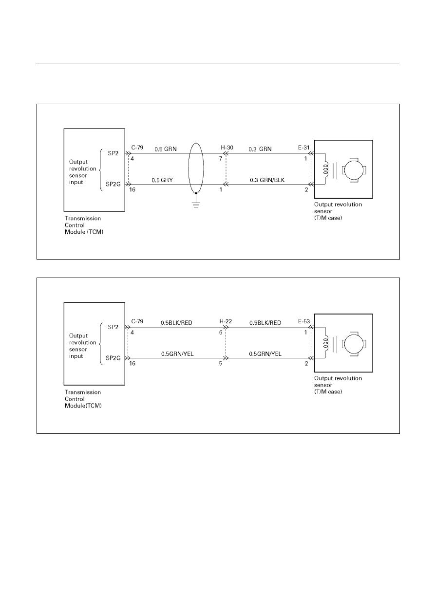
DTC P0722 (FLASHING CODE 11)
OUTPUT REVOLUTION SENSOR FAILURE (SP2)
UBS (For General Export)
D07R200060
TFR/S (For Australia) and TFR (For South Africa)
D07L200005
Нет комментариевНе стесняйтесь поделиться с нами вашим ценным мнением.
Текст