Isuzu D-Max / Isuzu Rodeo (TFR/TFS). Manual — part 235
ENGINE DRIVEABILITY AND EMISSIONS
6E–181
7
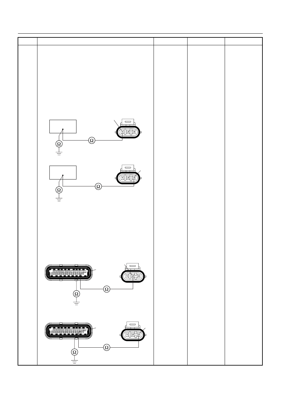
Using the DVM and check the ignition coil signal
circuit for the affected coil.
Breaker box is available:
1. Ignition “Off”, engine “Off”.
2. Install the breaker box as type A. (ECM
disconnected) Ref. 6E-80.
3. Disconnect the ignition coil module connector.
4. Check the circuit for open or short to ground circuit
for the affected coil.
Was the problem found?
Breaker box is not available:
1. Ignition “Off”, engine “Off”.
2. Disconnect the ignition coil module connector and
ECM connector.
3. Check the circuit for open or short to ground circuit
for the affected coil.
Was the problem found?
—
Repair faulty
harness and
verify repair
Go to Step 8
Step
Action
Value(s)
Yes
No
18
E-18
1
Coil 1
19
E-18
3
Coil 2
E-18
E-60(J1)
18
2
Coil 1
E-18
E-60(J1)
19
3
Coil 2
6E–182
ENGINE DRIVEABILITY AND EMISSIONS
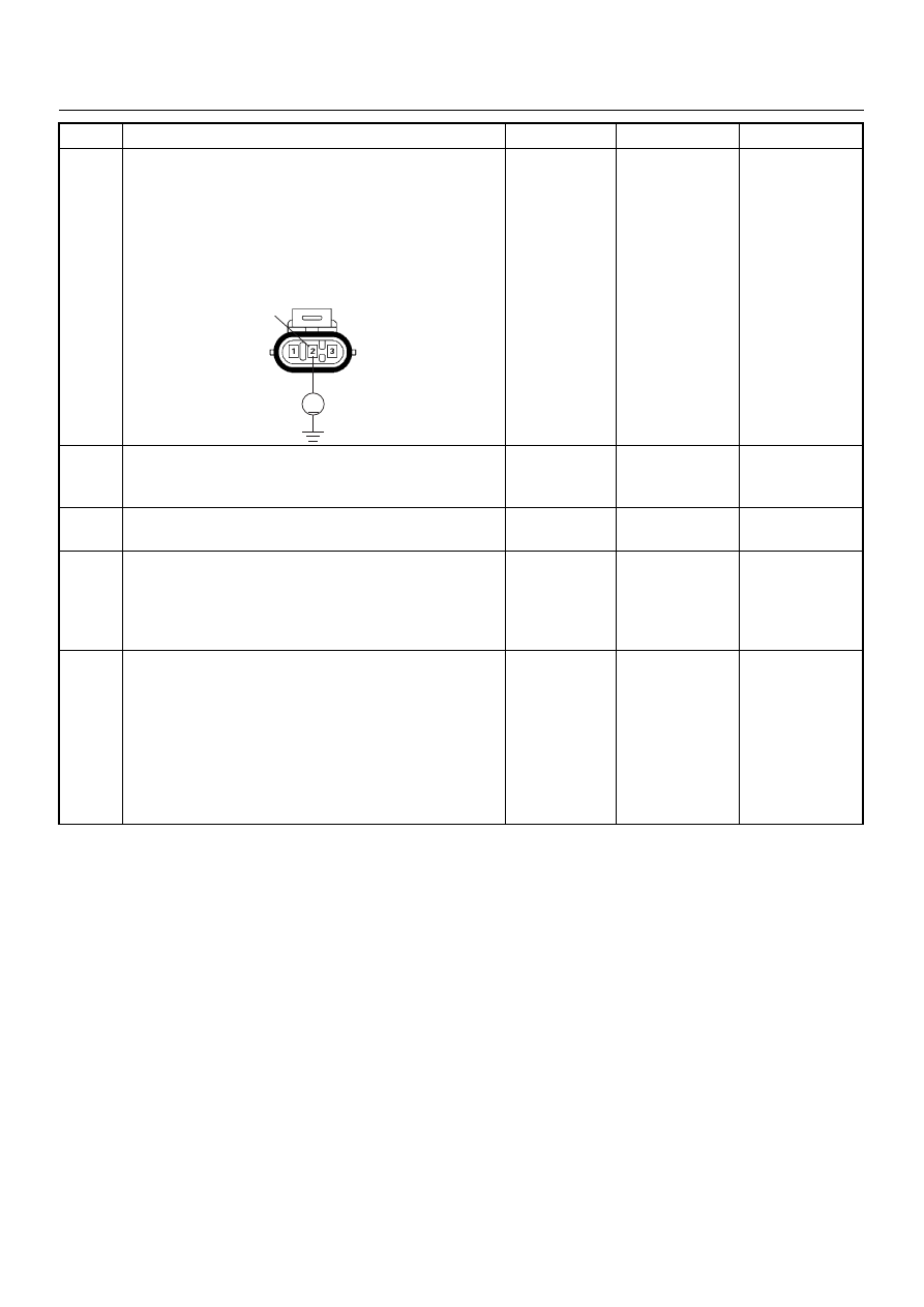
8
Using the DVM and check the ignition coil module
power supply circuit.
1. Ignition “On”, engine “Off”.
2. Disconnect the ignition coil module connector.
3. Check the circuit for open circuit.
Was the DVM indicated specified value?
Battery
voltage
Go to Step 10
Go to Step 9
9
Repair the open or short to ground circuit between the
“IGN. Coil” fuse (15A) and ignition coil module.
Is the action complete?
—
Verify repair
—
10
Replace the ignition coil module.
Was the problem solved?
—
Verify repair
Go to Step 11
11
Is the ECM programmed with the latest software
release?
If not, download the latest software to the ECM using
the “SPS (Service Programming System)”.
Was the problem solved?
—
Verify repair
Go to Step 12
12
Replace the ECM.
Is the action complete?
IMPORTANT: The replacement ECM must be
programmed. Refer to section of the Service
Programming System (SPS) in this manual.
Following ECM programming, the immobiliser system
(if equipped) must be linked to the ECM. Refer to
section 11 “Immobiliser System-ECM replacement” for
the ECM/Immobiliser linking procedure.
—
Verify repair
—
Step
Action
Value(s)
Yes
No
V
E-18
2
ENGINE DRIVEABILITY AND EMISSIONS
6E–183
DIAGNOSTIC TROUBLE CODE (DTC) P0443 EVAPORATIVE EMISSION (EVAP)
CONTROL SYSTEM PURGE CONTROL VALVE CIRCUIT MALFUNCTION
Condition for setting the DTC and action taken when the DTC sets
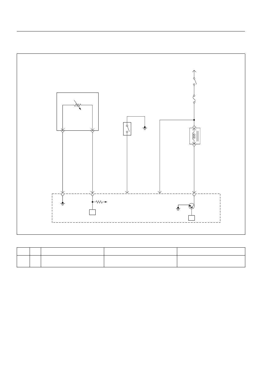
Circuit Description
The Engine Control Module (ECM) controls the
Evaporative Emission (EVAP) Canister Purge Solenoid
Valve through the use of a control (ground) circuit. If the
ECM commands the Purge solenoid to maximum duty
cycle (100%) but the voltage remains High (12 Volts); or,
if the ECM commands the Purge solenoid to minimum
duty cycle (0%) but the voltage remains Low (0 volts),
then DTC P0443 will set.
Diagnostic Aids
• Poor connections, or a damaged harness - Inspect
the harness connectors for: backed-out terminals,
improper mating or damaged terminals. Also check
for open circuits, shorts to ground, and shorts to
voltage.
Code
Type
DTC Name
DTC Setting Condition
Fail-Safe (Back Up)
P0443
B
EVAP Emission Control System Purge
Control Circuit
EVAP purge solenoid circuit open, short to
ground or short to voltage circuit.
No fail-safe function.
Intake
Air
Temperature(IAT)
Sensor
0.5
GRN
J2-1
0.5
YEL/
GRN
J2-22
0.5
GRN/
YEL
J2-20
0.5
BLU/
YEL
0.5
BLU/
YEL
Engine
15A
Ignition
SW
Battery Voltage
J2-3
0.5
GRN/
WHT
J1-5
+5V
µP
µP
Power
Steering
Pressure
SW
Evaporativ
Emission(EVAP)
Canistor
Purge
Valve
Solenoid
Engine
Control
Module
(ECM)
6E–184
ENGINE DRIVEABILITY AND EMISSIONS
Diagnostic Trouble Code (DTC) P0443
Evap Emission Control System Purge Control Circuit
Step
Action
Value(s)
Yes
No
1
Was the “On-Board Diagnostic (OBD) System Check”
performed?
—
Go to Step 2
Go to On Board
Diagnostic
(OBD) System
Check
2
1. Connect the Tech 2.
2. Review and record the failure information.
3. Select “F0: Read DTC Infor By Priority” in “F0:
Diagnostic Trouble Code”.
Is the DTC P0443 stored as “Present Failure”?
—
Go to Step 3
Refer to
Diagnostic Aids
and Go to Step
3
3
1. Using the Tech2, ignition “On” and engine “Off”.
2. Select “Clear DTC Information” with the Tech2 and
clear the DTC information.
3. Operate the vehicle and monitor the “F5: Failed
This Ignition” in “F2: DTC Information”.
Was the DTC P0443 stored in this ignition cycle?
—
Go to Step 4
Refer to
Diagnostic Aids
and Go to Step
4
4
Check for poor/faulty connection at the purge solenoid
valve or ECM connector. If a poor/faulty connection is
found, repair as necessary.
Was the problem found?
—
Verify repair
Go to Step 5
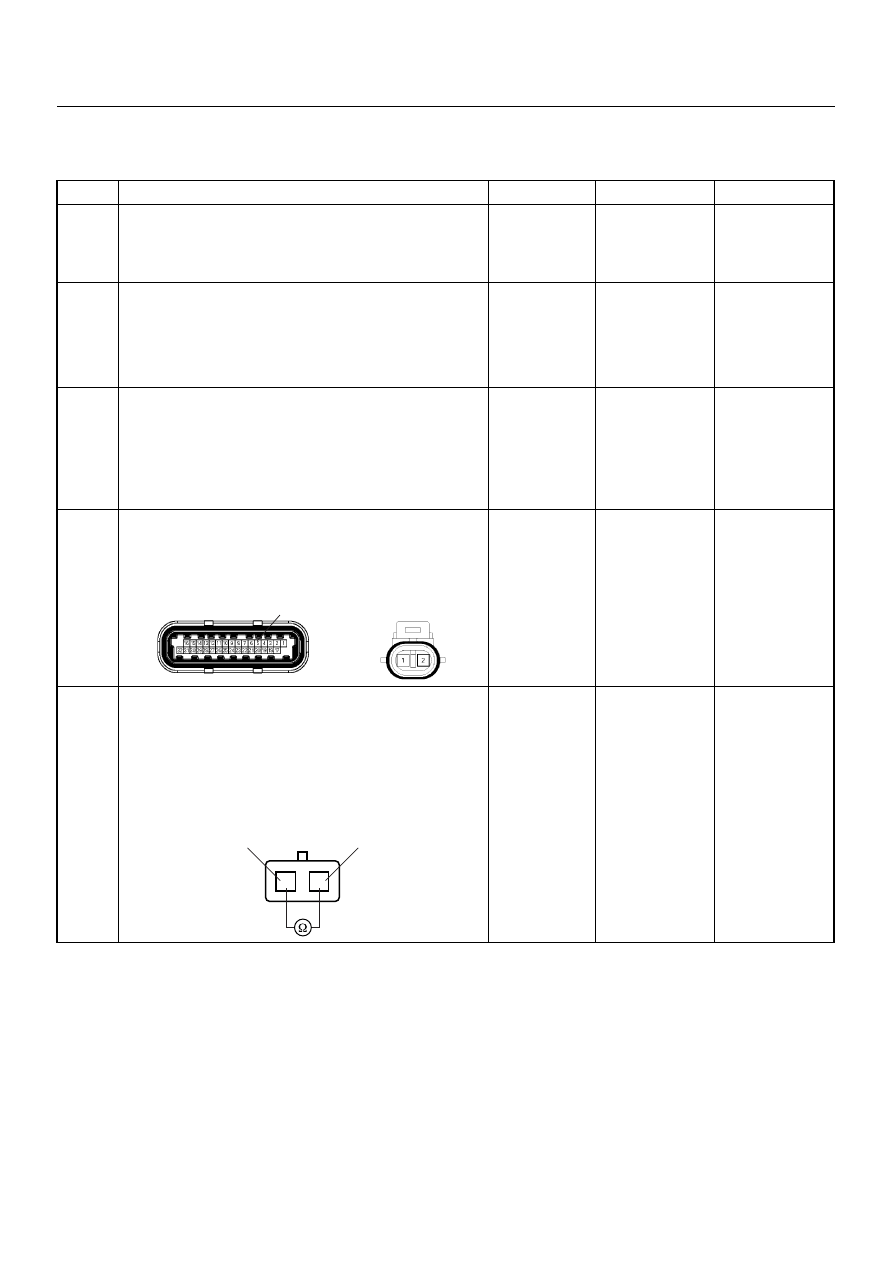
5
Using the DVM and check the purge solenoid valve.
1. Ignition “Off”, engine “Off”.
2. Disconnect purge solenoid valve connector.
3. Measure the resistance of purge solenoid valve
coil.
Does the tester indicate standard resistance?
25 - 30
Ω at
20°C
Go to Step 6
Go to Step 9
5
E-60(J1)
E-66
1
2
EVAP Purge Solenoid
1
2
Нет комментариевНе стесняйтесь поделиться с нами вашим ценным мнением.
Текст