Isuzu D-Max / Isuzu Rodeo (TFR/TFS). Manual — part 603
ENGINE ELECTRICAL 6D – 19
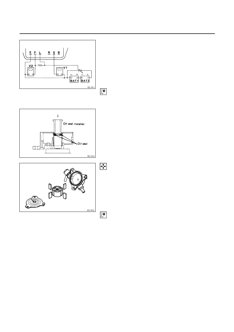
10. Repeat Steps 3 through 5 to measure the voltage
between terminals B, L, and E.
Refer to the illustration.
The regulator voltage should be between 0.5 and 3
volts higher than the measured voltage.
If the regulator voltage is outside this range, the
voltage regulator must be replaced.
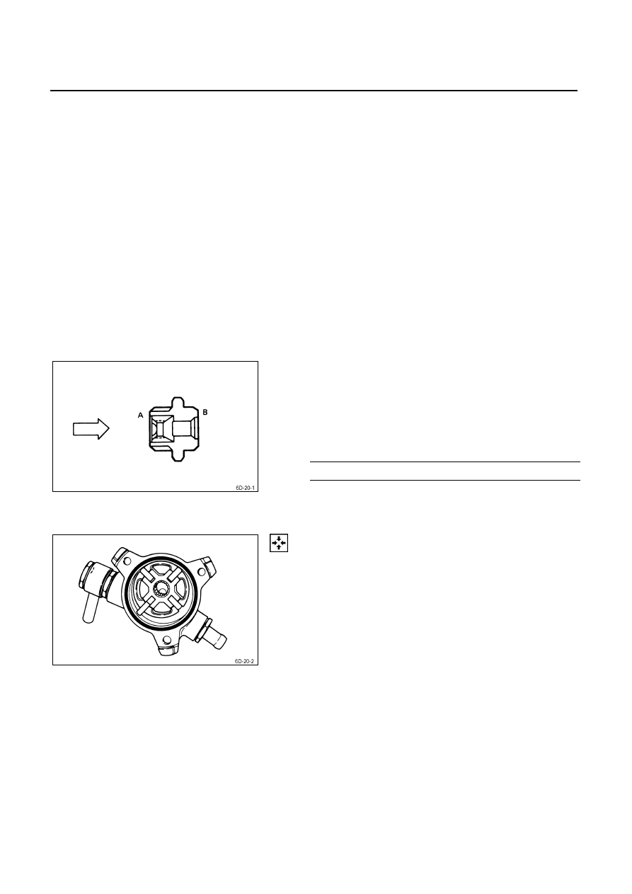
Oil Seal
Check the rear cover oil seal bore for oil leakage.
Oil Seal Replacement
1. Use a screwdriver to remove the oil seal from the rear
cover side.
Take care not to damage the oil seal bore.
2. Discard the used oil seal.
3. Use the oil seal installer to install the new oil seal.
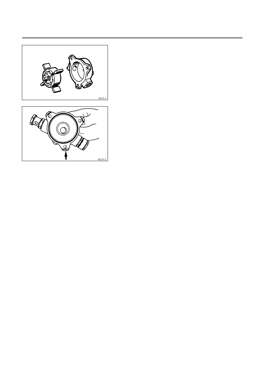
Vacuum Pump
Vacuum Pump Disassembly
1. Remove the center plate from the vacuum pump
housing.
2. Remove the vacuum pump rotor and the vanes from
the housing.
Inspection
Vacuum Pump Housing and Center Plate
Inspect the vacuum pump housing and the center plate for
excessive wear, abrasion, and scoring.
If any of these conditions are present, the vacuum pump
housing and center plate must be replaced.
6D – 20 ENGINE ELECTRICAL
Vane
Inspect the vanes for excessive wear and damage.
Replace all four vanes if either of these conditions are
present.
Never replace only one vane.
Rotor
1. Inspect the rotor for excessive wear, abrasion, and
scoring.
Pay particular attention to the internal spline.
Replace the rotor if any of these conditions are
present.
2. Inspect the generator rotor shaft splines for backlash.
Replace the rotor if backlash is present.
Check Value
1. Carefully force the valve from the “B” side as shown in
the illustration.
The valve must move smoothly.
If it does not, the check valve must be replaced.
2. Apply compressed air to the “A” side.
Air Pressure
kg/cm
2
(psi/kPa)
1-5 (14 – 71/98 - 490)
Check for air leakage from the check valve.
If there is air leakage, the valve must be replaced.
Vacuum Pump Reassembly
1. Install the vanes to the rotor slits.
The rounded side of the vanes must be facing the
rotor housing.
ENGINE ELECTRICAL 6D – 21
2. Install the rotor with the concave side facing the center
plate.
3. Install the center plate to the rotor housing.
Be sure to use a new O-ring.

6D – 22 ENGINE ELECTRICAL
REASSEMBLY
Reassembly Steps
1. Rear cover
14.
Bearing retainer
J
2. Lead wire
J
15.
Rotor assembly
J
3. IC regulator assembly
16.
Ball bearing
4. Brush holder
17.
Rotor
5. Holder plate
18.
Spacer
J
6. Diode
J
19.
Pulley assembly
J
7. Stator
20.
Fan
8. Screw
21.
Pulley
9. Condenser
22.
Nut and washer
10. Terminal bolt and nut
J
23.
Through bolt
11. Front cover assembly
J
24.
Brush
12. Front cover
J
25.
Cover
13. Ball bearing
J
26.
Vacuum pump
Нет комментариевНе стесняйтесь поделиться с нами вашим ценным мнением.
Текст