Isuzu D-Max / Isuzu Rodeo (TFR/TFS). Manual — part 604
ENGINE ELECTRICAL 6D – 23
Important Operations
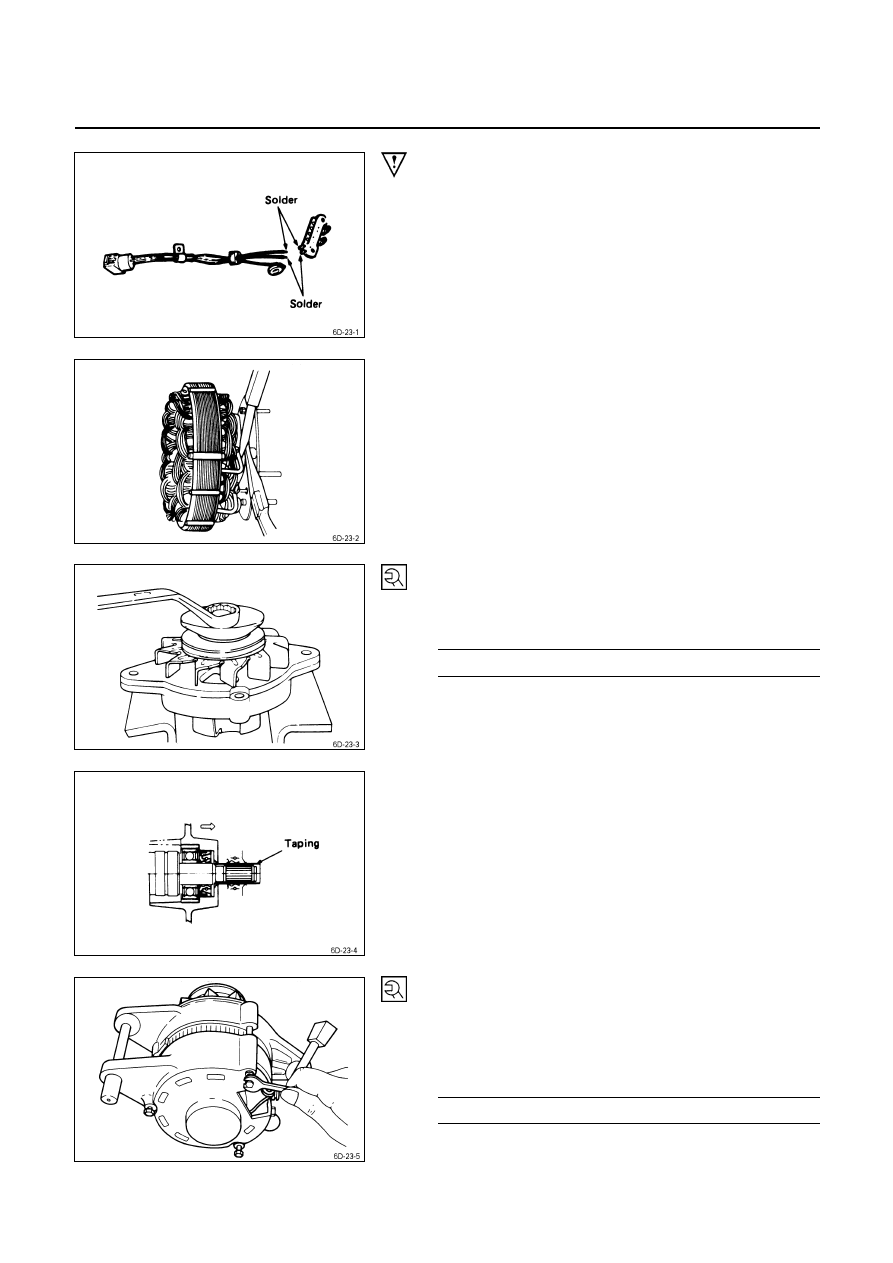
2. Lead
Wire
3. IC
Regulator
Solder the IC regulator lead wires.
6. Diode
7. Stator
Use a pair of long-nose plier to connect the stator coil
leads and the diode leads.
Finish the work as quickly as possible to prevent the diode
from heat transferred by the soldering.
15. Rotor Assembly
19. Pulley Assembly
Clamp the rotor in a vise and install the pulley nut.
Pulley Nut Torque
kg
⋅m(lb⋅ft)
5.0
± 1.0 (36.2 ± 7.2/49.0 ± 9.8)
Remove the tape from the splines.
23. Through Bolt
1. Place a pilot bar into the through bolt hole to align the
front cover and the rear cover.
2. Install the through bolts and tighten them to the
specified torque.
Through Bolt Torque
kg
⋅m(lb⋅ft)
0.65
± 0.5 (4.7 ± 3.6/6.3 ± 4.9)
6D – 24 ENGINE ELECTRICAL
24. Brush
Install the brush into the brush holders.
25. Cover
Install the brush cover and tighten the cover bolts to the
specified torque.
Brush Cover Bolt Torque
kg
⋅m(lb⋅ft)
0.35
± 0.5 (2.5 ± 3.6/3.4 ± 5.0)
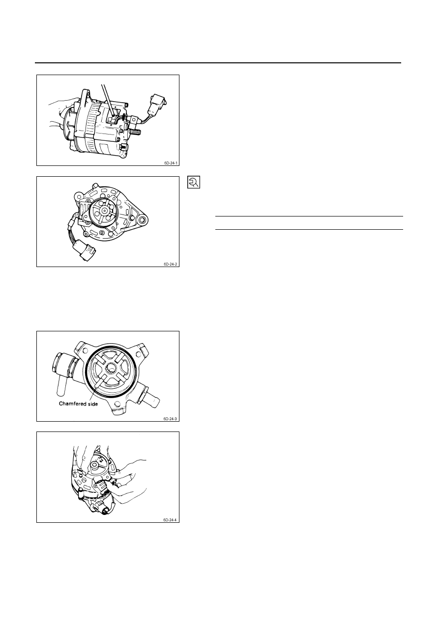
26. Vaccum Pump
Position the rotor, with the serrated boss turned up, on the
center plate and housing.
Align the holes in the center plate and the rotor.
Install vanes into slits in rotor.
The vanes should be installed with the chamfered side
facing outward.
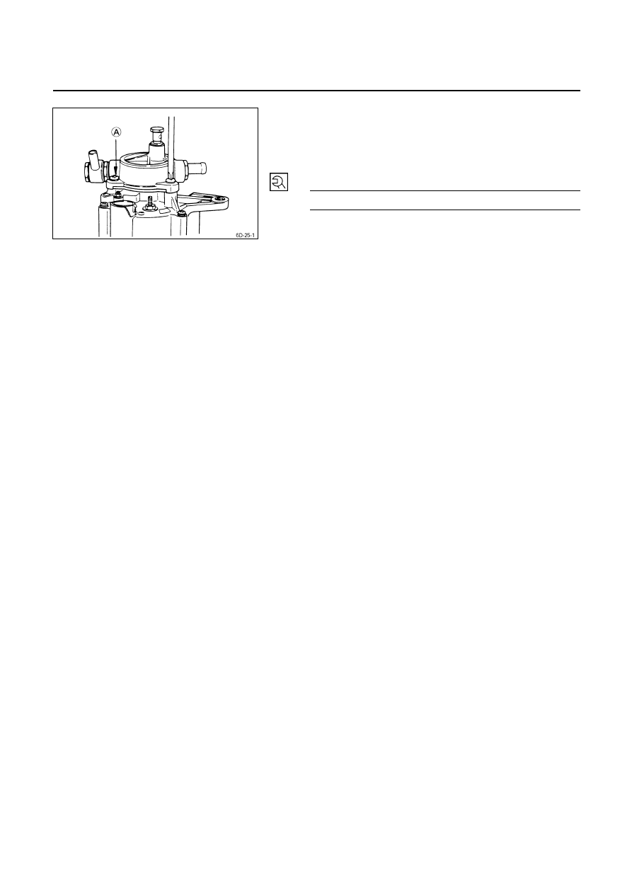
Install the vacuum pump housing.
Make sure that the O-ring is not projecting beyond the
slots of the center plate.
Take care so that no scratching takes place on the vane
resulted by contact with the housing.
ENGINE ELECTRICAL 6D – 25
Install the housing in the generator and fix it with the three
bolts.
Supply engine oil (5cc or so) from the oil port and check
that the generator pulley can be turned smoothly with your
hand.
Generator Housing Bolt Torque
kg
⋅m(lb⋅ft)
0.65
± 0.5 (4.7 ± 3.6/6.3 ± 4.9)
6D – 26 ENGINE ELECTRICAL
STARTER MOTOR
REMOVAL AND INSTALLATION
Read this Section carefully before performing any removal and installation procedure. This Section gives you
important points as well as the order of operation. Be sure that you understand everything in this Section before you
begin.
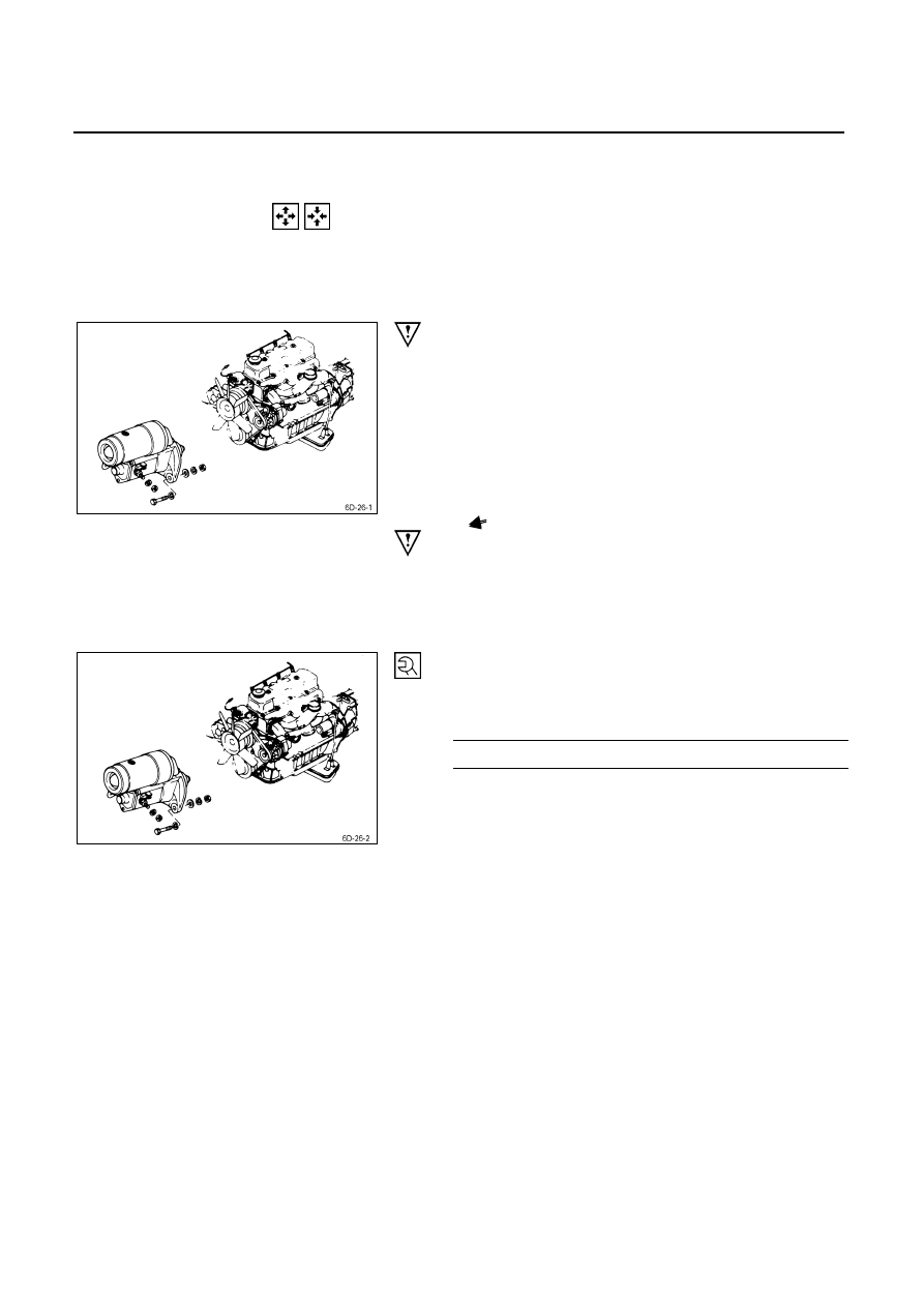
Important Operations - Removal
Starter Motor
1) Disconnect the battery cable and the ground cable at
the battery terminals.
2) Disconnect the magnetic switch cable at the terminal
bolts.
3) Disconnect the battery cable at the starter motor and
the ground cable at the cylinder body.
4) Remove the starter motor from the engine.
Important Operations – Installation
Follow the removal procedure in the reverse order to
perform the installation procedure. Pay careful attention to
the important points during the installation procedure.
Starter Motor
1) Install the starter motor to the rear plate.
2) Tighten the starter motor bolts to the specified torque.
Starter Motor Bolt Torque
kg
⋅m(lb⋅ft/N⋅m)
7
± 1 (50.6 ± 7.2/68.7 ± 9.8)
3) Reconnect the battery cable at the starter motor and
the ground cable at the cylinder body.
4) Reconnect the battery cable and the ground cable at
the battery terminals.
Нет комментариевНе стесняйтесь поделиться с нами вашим ценным мнением.
Текст