Isuzu D-Max / Isuzu Rodeo (TFR/TFS). Manual — part 602

ENGINE ELECTRICAL 6D – 15
INSPECTION AND REPAIR
Make the necessary adjustments, repairs, and part replacement if excessive wear or damage is discovered during
inspection.
ROTOR ASSEMBLY
1. Inspect the slip ring faces for dirt and pitting.
Wipe away any dirt with a clean cloth soaked in
alcohol.
2. Measure the slip ring diameter.
Slip Ring Diameter
mm (in)
Standard Limit
31.6 (1.245)
30.6 (1.183)
If the slip ring diameter is less than the specified limit, the
slip rings must be replaced.
3. Measure the rotor coil resistance.
Rotor Coil Resistance at 20
°C (68°F) ohms
Standard 4.2
4. Check for continuity between the slip rings and the
rotor core or shaft.
If there is continuity, the entire rotor assmbly must be
replaced.

6D – 16 ENGINE ELECTRICAL
STATOR COIL ASSEMBLY
1. Check for continuity across the stator coils.
If there is no continuity, the stator coils must be
replaced.
Resistance Between The Terminal “N” and the Coil Ends
(Reference) ohms
Standard 0.1
2. Check for continuity between each stator coils and the
stator core.
If there is continuity, the stator coils must be replaced.
BRUSH
Each brush has a line to indicate whether or not the brush
is serviceable.
If the line is not visible, the brush must be replaced.
Brush Length (Reference)
mm (in)
Standard Limit
20 (0.8)
6 (0.2)
DIODE
1. Check for continuity between the battery and each of
the three stator coil lead terminals.
If there is continuity, the diode is normal.
If there is no continuity, the diode must be replaced.
2. Reverse the polarity of the test probes.
If there is no continuity, the diode is normal.
If there is continuity, the diode must be replaced.
ENGINE ELECTRICAL 6D – 17
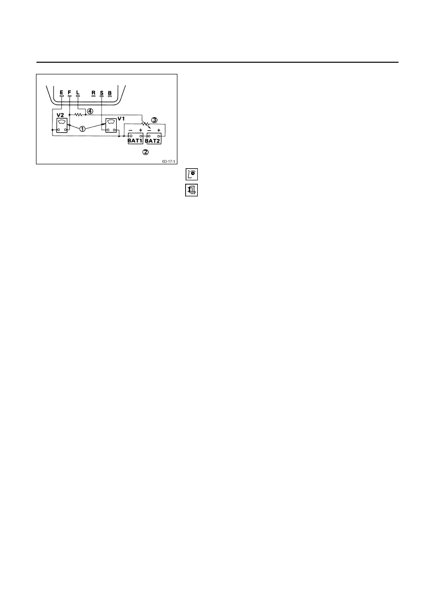
IC REGULATOR
The IC regulator may be tested with either a circuit tester
or a pair of standard voltmeters.
Refer to the illustration.
(1) Circuit tester (or voltmeter) range is from 0 to 50 volts
in 0.5 volt increments.
(2) Two 12-volt batteries are required.
(3) Note the variable resistor.
(4) This resistor is rated at 100 watts or 3 ohms.
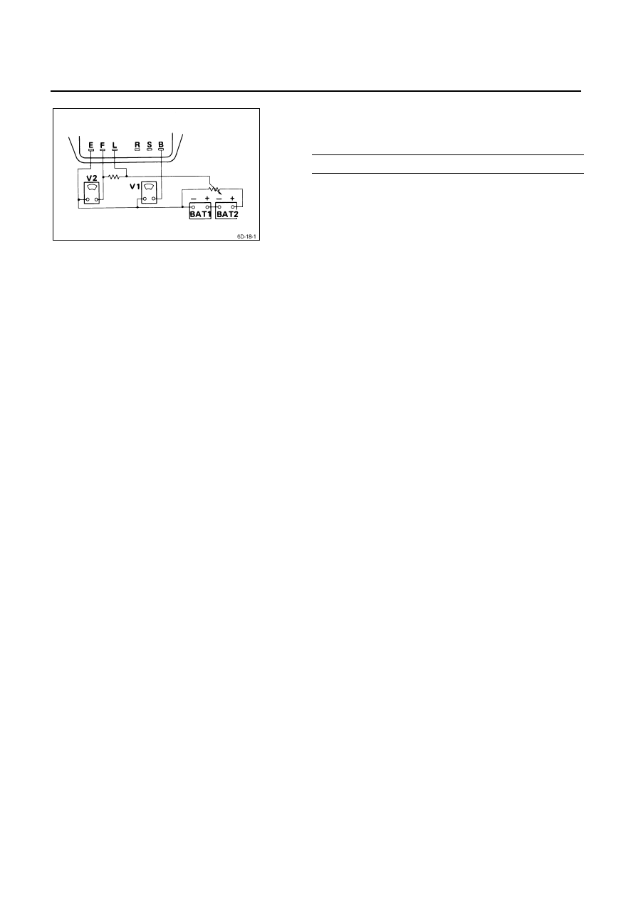
Testing the IC Regulator
Refer to the wiring diagram in the illustration when testing
the IC regulator.
6D – 18 ENGINE ELECTRICAL
1. Connect the batteries in series.
2. Measure the battery power (Voltage).
Battery Power
V
20 – 26
3. Connect the circuit tester (or voltmeter V2) as shown
in the illustration.
4. Set the variable resistor (3) to zero.
5. Slowly increase the resistance of the variable resistor
toward the build-up point.
Measure the voltage between E and F.
As long as the resistance is below the build-up point,
the voltage reading should be stable and less than two
volts.
When the resistance exceeds the build-up point, the
voltage reading should be two volts or greater.
If the voltage does not exceed two volts after reaching
the build-up point, the IC regulator must be replaced.
6. Return the variable resistor to zero.
7. Connect the circuit tester (or voltmeter V1) as shown
in the illustration.
8. Measure the voltage at terminals S, L, and E.
9. Slowly increase the resistance of the variable resistor.
Note the point at which the voltage quickly builds up to
between 2 and 6 volts.
This will indicate the point at which the voltage
regulator begins to function.
If the measured voltage is outside the specified range,
the voltage regulator must be replaced.
Нет комментариевНе стесняйтесь поделиться с нами вашим ценным мнением.
Текст