Isuzu D-Max / Isuzu Rodeo (TFR/TFS). Manual — part 599
ENGINE ELECTRICAL 6D – 3
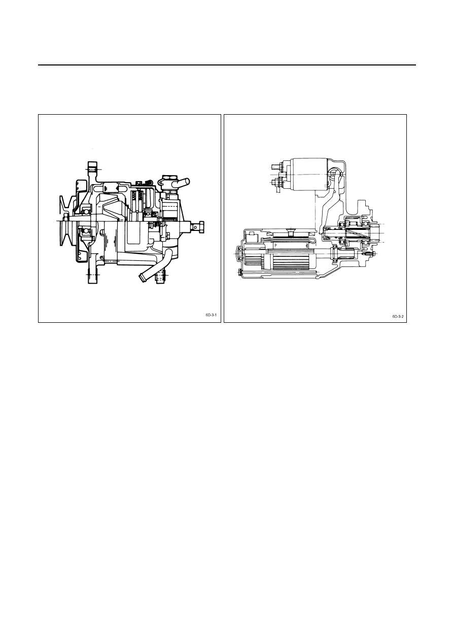
GENERAL DESCRIPTION
GENERATOR STARTER
MOTOR
The basic charging system is the IC integral regulator charging system. The internal components are connected
electrically as shown in charging circuit diagram.
The generator features a solid state regulator that is mounted inside the generator. All regulator components are
enclosed into a solid mold, and this unit along with the brush holder assembly is attached to the slip ring end frame.
The generator voltage setting cannot be adjusted.
The starter motor circuit is composed of a 4-pole 4-brush type direct current series motor, starter switch with safety
lock, etc. The starter motor circuit utilizes negative ground polarity.
6D – 4 ENGINE ELECTRICAL
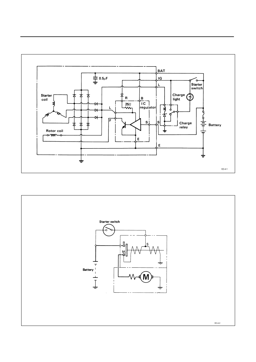
CHARGING CIRCUIT DIAGRAM
STARTING CIRCUIT DIAGRAM

ENGINE ELECTRICAL 6D – 5
WIRE CODING
DESCRIPTION
Codes used in the circuit diagram represent wire size and
color
.
Example: 0.5 R
Wire
color
(Red)
Wire size (0.5 mm
2
)
WIRE SIZE
Wire size is specified with the metric gauge system.
The metric gauge system gives the wire size in cross-
sectional area measured in square millimeters.
WIRE SIZE SPECIFICATIONS
Wire size
mm
2
AWG
Number of wires/
Wire diameter
mm (in.)
Resistance at normal room
temperature of 20
°C (68°F)
Ω/m (Ω/ft.)
Maximum allowable
current
A
0.5
0.85
1.25
2
3
5
8
15
20
30
20
18
16
14
12
10
8
6
4
2
7/0.32 (0.013)
11/0.32 (0.013)
16/0.32 (0.013)
26/0.32 (0.013)
41/0.32 (0.013)
65/0.32 (0.013)
50/0.45 (0.018)
84/0.45 (0.018)
41/0.80 (0.031)
70/0.80 (0.031)
0.03250 (0.00991)
0.02050 (0.00625)
0.01410 (0.00430)
0.00867 (0.00264)
0.00550 (0.00168)
0.00347 (0.00106)
0.00228 (0.00070)
0.00136 (0.00042)
0.00087 (0.00027)
0.00051 (0.00016)
11.3
14.8
18.8
25.4
34.2
45.9
59.8
82.8
110.9
147.0
6D – 6 ENGINE ELECTRICAL
WIRE COLOR
All wires have color-coded insulation.
Wires belonging to a system’s main harness will have a
single color
.
Wires belonging to a system’s sub-circuits will have a
colored stripe
.
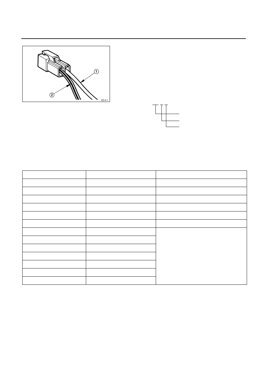
Striped wires use the following code to show wire size and
colors.
Example: 0.5 G R
Wire size (0.5 mm
2
)
Green
(Base
color)
Red (Stripe color)
Abbreviations are used to indicate wire color within a
circuit diagram.
Refer to the following table.
WIRE COLOR-CODING
Color-coding Meaning
Circuits
B
Black
Starter circuit and grounding circuit
W White
Charging
circuit
R Red
Lighting
circuit
G Green
Signal
circuit
Y Yellow
Instrument
circuit
L Blue
Wiper
circuit
O Orange
Br Brown
Lg Light
green
Gy Grey
P Pink
Sb Sky
blue
V Violet
Other circuits
Нет комментариевНе стесняйтесь поделиться с нами вашим ценным мнением.
Текст