Isuzu D-Max / Isuzu Rodeo (TFR/TFS). Manual — part 148

6E–196
4JH1 ENGINE DRIVEABILITY AND EMISSIONS
7
Replace the ECM.
Is the action complete?
IMPORTANT: The replacement ECM must be
programmed. Refer to section of the Service
Programming System (SPS) in this manual.
Following ECM programming, the immobiliser system
(if equipped) must be linked to the ECM. Refer to
section 11 “Immobiliser System-ECM replacement” for
the ECM/Immobiliser linking procedure.
—
Verify repair
—
Step
Action
Value(s)
Yes
No
4JH1 ENGINE DRIVEABILITY AND EMISSIONS
6E–197
Diagnostic Trouble Code (DTC) P0560 (Symptom Code 2) (Flash Code 35)
System Voltage Too Low
Step
Action
Value(s)
Yes
No
1
Was the “On-Board Diagnostic (OBD) System Check”
performed?
—
Go to Step 2
Go to On Board
Diagnostic
(OBD) System
Check
2
1. Connect the Tech 2.
2. Review and record the failure information.
3. Select “F0: Read DTC Infor As Stored By ECU” in
“F0: Diagnostic Trouble Codes”.
Is the DTC P0560 (Symptom Code 2) stored as
“Present Failure”?
—
Go to Step 3
Refer to
Diagnostic Aids
and Go to Step
3
3
1. Using the Tech 2, ignition “On” and engine “Off”.
2. Select “F1: Clear DTC Information” in “F0:
Diagnostic Trouble Codes” with the Tech 2 and
clear the DTC information.
3. Operate the vehicle and monitor the “F0: Read
DTC Infor As Stored By ECU” in the “F0:
Diagnostic Trouble Codes”.
Was the DTC P0560 (Symptom Code 2) stored in this
ignition cycle?
—
Go to Step 4
Refer to
Diagnostic Aids
and Go to Step
4
4
1. Using the Tech 2, ignition “On” and engine “On”.
2. Monitor the “System Voltage” in the data display.
3. Load the electrical system by turning on the
headlights, etc..
Does the Tech 2 indicate enough ignition voltage?
10 - 14V
Go to Step 6
Go to Step 5
5
Using the DVM and check the battery voltage at the
battery terminal.
Does the tester indicate enough battery voltage?
10 - 14V
Go to Step 6
Check the
charging
system, charge
or replace the
battery
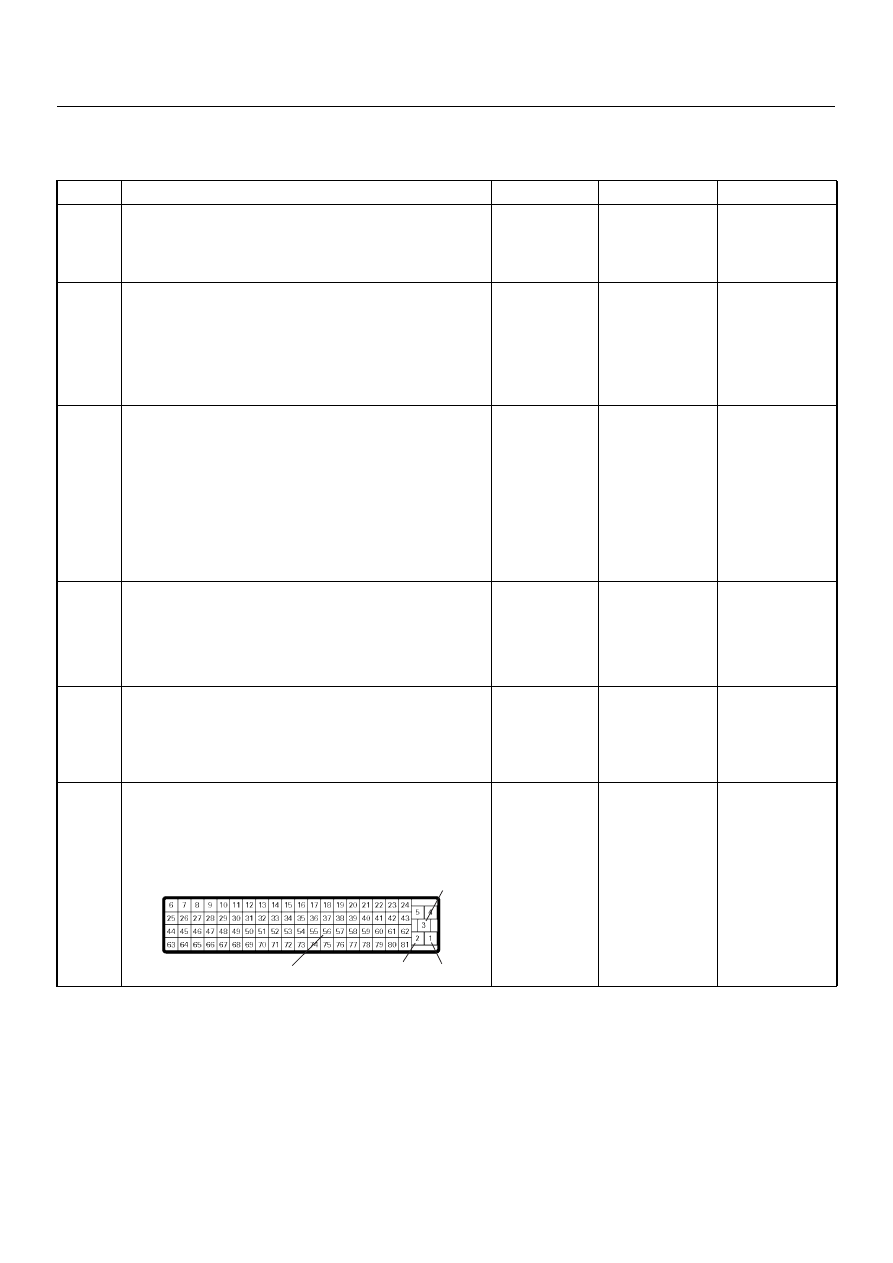
6
Check for poor/faulty connection at the ECM
connector. If a poor/faulty connection is found, repair
as necessary.
Was the problem found?
—
Verify repair
Go to Step 7
3
2
1
56
C-56

6E–198
4JH1 ENGINE DRIVEABILITY AND EMISSIONS
7
Using the DVM and check the ECM main relay.
1. Ignition “Off”, engine “Off”.
2. Remove the ECM main relay from the relay box.
3. Check the relay coil.
Was the DVM indicated specified value?
Continuity
Go to Step 8
Replace ECM
main relay and
verify repair
8
Check for poor/faulty connection of the ECM ground at
the body. If a poor/faulty connection is found, repair as
necessary.
Was the problem found?
—
Verify repair
Go to Step 9
9
Is the ECM programmed with the latest software
release?
If not, download the latest software to the ECM using
the “SPS (Service Programming System)”.
Was the problem solved?
—
Verify repair
Go to Step 10
10
Replace the ECM.
Is the action complete?
IMPORTANT: The replacement ECM must be
programmed. Refer to section of the Service
Programming System (SPS) in this manual.
Following ECM programming, the immobiliser system
(if equipped) must be linked to the ECM. Refer to
section 11 “Immobiliser System-ECM replacement” for
the ECM/Immobiliser linking procedure.
—
Verify repair
—
Step
Action
Value(s)
Yes
No
ECM Main Relay
3
4
C-109

4JH1 ENGINE DRIVEABILITY AND EMISSIONS
6E–199
Diagnostic Trouble Code (DTC) P0560 (Symptom Code A) (Flash Code 35)
System Voltage Malfunction (PSG)
Step
Action
Value(s)
Yes
No
1
Was the “On-Board Diagnostic (OBD) System Check”
performed?
—
Go to Step 2
Go to On Board
Diagnostic
(OBD) System
Check
2
1. Connect the Tech 2.
2. Review and record the failure information.
3. Select “F0: Read DTC Infor As Stored By ECU” in
“F0: Diagnostic Trouble Codes”.
Is the DTC P0560 (Symptom Code A) stored as
“Present Failure”?
—
Go to Step 3
Refer to
Diagnostic Aids
and Go to Step
3
3
1. Using the Tech 2, ignition “On” and engine “Off”.
2. Select “F1: Clear DTC Information” in “F0:
Diagnostic Trouble Codes” with the Tech 2 and
clear the DTC information.
3. Operate the vehicle and monitor the “F0: Read
DTC Infor As Stored By ECU” in the “F0:
Diagnostic Trouble Codes”.
Was the DTC P0560 (Symptom Code A) stored in this
ignition cycle?
—
Go to Step 4
Refer to
Diagnostic Aids
and Go to Step
4
4
Check for poor/faulty connection at the PSG (pump
control unit) connector. If a poor/faulty connection is
found, repair as necessary.
Was the problem found?
—
Verify repair
Go to Step 5
5
Using the DVM and check the PSG (pump control
unit) power supply circuit.
1. Ignition “On”, engine “Off”.
2. Disconnect the PSG (pump control unit)
connector.
3. Check the PSG (pump control unit) power supply
circuit.
Was the DVM indicated specified value?
10 - 14V
Go to Step 7
Go to Step 6
6
7
E-6
6
7
V
E-6
Нет комментариевНе стесняйтесь поделиться с нами вашим ценным мнением.
Текст