Isuzu D-Max / Isuzu Rodeo (TFR/TFS). Manual — part 153
6E–216
4JH1 ENGINE DRIVEABILITY AND EMISSIONS
3
1. Using the Tech 2, ignition “On” and engine “Off”.
2. Select “F1: Clear DTC Information” in “F0:
Diagnostic Trouble Codes” with the Tech 2 and
clear the DTC information.
3. Operate the vehicle and monitor the “F0: Read
DTC Infor As Stored By ECU” in the “F0:
Diagnostic Trouble Codes”.
Was the DTC P0703 (Symptom Code A) stored in this
ignition cycle?
—
Go to Step 4
Refer to
Diagnostic Aids
and Go to Step
4
4
Check the “Stop Lamp fuse (15A)”.
If the fuse is burnt out, repair as necessary.
Was the problem found?
—
Verify repair
Go to Step 5
5
Check for poor/faulty connection at the brake switch or
ECM connector. If a poor/faulty connection is found,
repair as necessary.
Was the problem found?
—
Verify repair
Go to Step 6
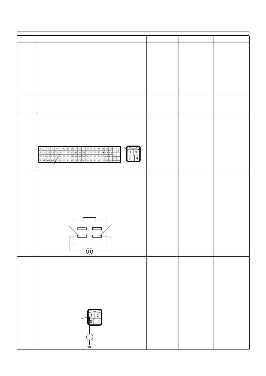
6
Using the DVM and check the brake switch 1.
1. Ignition “Off”, engine “Off”.
2. Remove the brake switch connector at the brake
pedal.
3. Check the brake switch 1.
Was the DVM indicated specified value?
Pedal is not
stepped on:
Continuity
Pedal stepped
on: No
continuity Go
to
Step 7
Replace pedal
switch and
verify repair
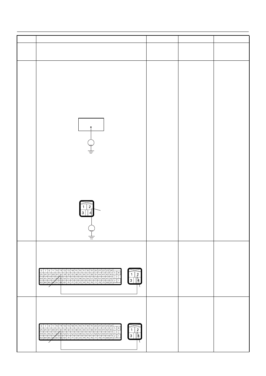
7
Using the DVM and check the brake switch 1 power
supply circuit.
1. Ignition “Off”, engine “Off”.
2. Remove the brake switch connector from the
brake switch.
3. Check the circuit for open circuit.
Was the DVM indicated specified value?
Battery
voltage
Go to Step 9
Go to Step 8
Step
Action
Value(s)
Yes
No
30
1
2
C-56
C-44
Brake Switch
3
4
V
1
C-44
4JH1 ENGINE DRIVEABILITY AND EMISSIONS
6E–217
8
Repair the open circuit between the “Stop Lamp fuse
(15A)” and brake switch 1.
Is the action complete?
—
Verify repair
—
9
Using the DVM and check the brake switch 1 circuit.
Breaker box is available:
1. Ignition “Off”, engine “Off”.
2. Install the breaker box as type B. (ECM
connected) Ref. Page 6E-73
3. Ignition “On”, engine “Off”.
4. Check the circuit for open or short to voltage
circuit.
Was the DVM indicated specified value?
Breaker box is not available:
1. Ignition “On”, engine “Off”.
2. Back probe the DVM to the brake switch 1 and
check the circuit for open or short to voltage
circuit.
Was the problem found?
Pedal is not
stepped on:
Less than 1V
Pedal stepped
on: Battery
voltage Go
to
Step 12
Fixed at battery
voltage: Go to
Step 10
Fixed at less
than 1V: Go to
Step 11
10
Repair the short to voltage circuit between the brake
switch 1 connector and ECM.
Is the action complete?
—
Verify repair
—
11
Repair the open circuit between the brake switch 1
connector and ECM.
Is the action complete?
—
Verify repair
—
Step
Action
Value(s)
Yes
No
30
V
V
2
C-44
2
30
C-56
C-44
2
30
C-56
C-44

6E–218
4JH1 ENGINE DRIVEABILITY AND EMISSIONS
12
Is the ECM programmed with the latest software
release?
If not, download the latest software to the ECM using
the “SPS (Service Programming System)”.
Was the problem solved?
—
Verify repair
Go to Step 13
13
Replace the ECM.
Is the action complete?
IMPORTANT: The replacement ECM must be
programmed. Refer to section of the Service
Programming System (SPS) in this manual.
Following ECM programming, the immobiliser system
(if equipped) must be linked to the ECM. Refer to
section 11 “Immobiliser System-ECM replacement” for
the ECM/Immobiliser linking procedure.
—
Verify repair
—
Step
Action
Value(s)
Yes
No
4JH1 ENGINE DRIVEABILITY AND EMISSIONS
6E–219
Diagnostic Trouble Code (DTC) P0703 (Symptom Code B) (Flash Code 25)
Brake Switch Malfunction
Step
Action
Value(s)
Yes
No
1
Was the “On-Board Diagnostic (OBD) System Check”
performed?
—
Go to Step 2
Go to On Board
Diagnostic
(OBD) System
Check
2
1. Connect the Tech 2.
2. Review and record the failure information.
3. Select “F0: Read DTC Infor As Stored By ECU” in
“F0: Diagnostic Trouble Codes”.
Is the DTC P0703 (Symptom Code B) stored as
“Present Failure”?
—
Go to Step 3
Refer to
Diagnostic Aids
and Go to Step
3
3
1. Using the Tech 2, ignition “On” and engine “Off”.
2. Select “F1: Clear DTC Information” in “F0:
Diagnostic Trouble Codes” with the Tech 2 and
clear the DTC information.
3. Operate the vehicle and monitor the “F0: Read
DTC Infor As Stored By ECU” in the “F0:
Diagnostic Trouble Codes”.
Was the DTC P0703 (Symptom Code B) stored in this
ignition cycle?
—
Go to Step 4
Refer to
Diagnostic Aids
and Go to Step
4
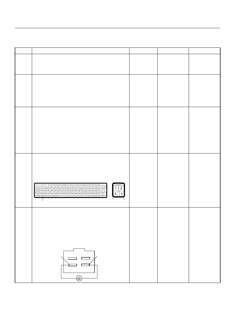
4
Check for poor/faulty connection at the brake switch or
ECM connector. If a poor/faulty connection is found,
repair as necessary.
Was the problem found?
—
Verify repair
Go to Step 5
5
Using the DVM and check the brake switch 2.
1. Ignition “Off”, engine “Off”.
2. Remove the brake switch connector at the brake
pedal.
3. Check the brake switch 2.
Was the DVM indicated specified value?
Pedal is not
stepped on:
No continuity
Pedal stepped
on: Continuity
Go to Step 6
Replace pedal
switch and
verify repair
65
3
4
C-56
C-44
Brake Switch
3
4
Нет комментариевНе стесняйтесь поделиться с нами вашим ценным мнением.
Текст