Isuzu D-Max / Isuzu Rodeo (TFR/TFS). Manual — part 151

6E–208
4JH1 ENGINE DRIVEABILITY AND EMISSIONS
Diagnostic Trouble Code (DTC) P0606 (Symptom Code B) (Flash Code 28) ECU
Malfunction
Step
Action
Value(s)
Yes
No
1
Was the “On-Board Diagnostic (OBD) System Check”
performed?
—
Go to Step 2
Go to On Board
Diagnostic
(OBD) System
Check
2
1. Connect the Tech 2.
2. Review and record the failure information.
3. Select “F0: Read DTC Infor As Stored By ECU” in
“F0: Diagnostic Trouble Codes”.
Is the DTC P0606 (Symptom Code B) stored as
“Present Failure”?
—
Go to Step 3
Refer to
Diagnostic Aids
and Go to Step
3
3
1. Using the Tech 2, ignition “On” and engine “Off”.
2. Select “F1: Clear DTC Information” in “F0:
Diagnostic Trouble Codes” with the Tech 2 and
clear the DTC information.
3. Operate the vehicle and monitor the “F0: Read
DTC Infor As Stored By ECU” in the “F0:
Diagnostic Trouble Codes”.
Was the DTC P0606 (Symptom Code B) stored in this
ignition cycle?
—
Go to Step 4
Refer to
Diagnostic Aids
4
Is the ECM programmed with the latest software
release?
If not, download the latest software to the ECM using
the “SPS (Service Programming System)”.
Was the problem solved?
—
Verify repair
Go to Step 5
5
Substitute a known good ECM and recheck.
Was the problem solved?
IMPORTANT: The replacement ECM must be
programmed. Refer to section of the Service
Programming System (SPS) in this manual.
Following ECM programming, the immobiliser system
(if equipped) must be linked to the ECM. Refer to
section 11 “Immobiliser System-ECM replacement” for
the ECM/Immobiliser linking procedure.
—
Go to Step 6
Go to Step 7
6
Replace the ECM.
Is the action complete?
IMPORTANT: The replacement ECM must be
programmed. Refer to section of the Service
Programming System (SPS) in this manual.
Following ECM programming, the immobiliser system
(if equipped) must be linked to the ECM. Refer to
section 11 “Immobiliser System-ECM replacement” for
the ECM/Immobiliser linking procedure.
—
Verify repair
—
7
Replace the injection pump assembly.
Is the action complete?
—
Verify repair
—
4JH1 ENGINE DRIVEABILITY AND EMISSIONS
6E–209
DIAGNOSTIC TROUBLE CODE (DTC) P0645 (SYMPTOM CODE 4)
(FLASH CODE 46) A/C COMPRESSOR RELAY CIRCUIT VOLTAGE LOW
DIAGNOSTIC TROUBLE CODE (DTC) P0645 (SYMPTOM CODE 8)
(FLASH CODE 46) A/C COMPRESSOR RELAY CIRCUIT VOLTAGE HIGH
Condition for setting the DTC and action taken when the DTC sets
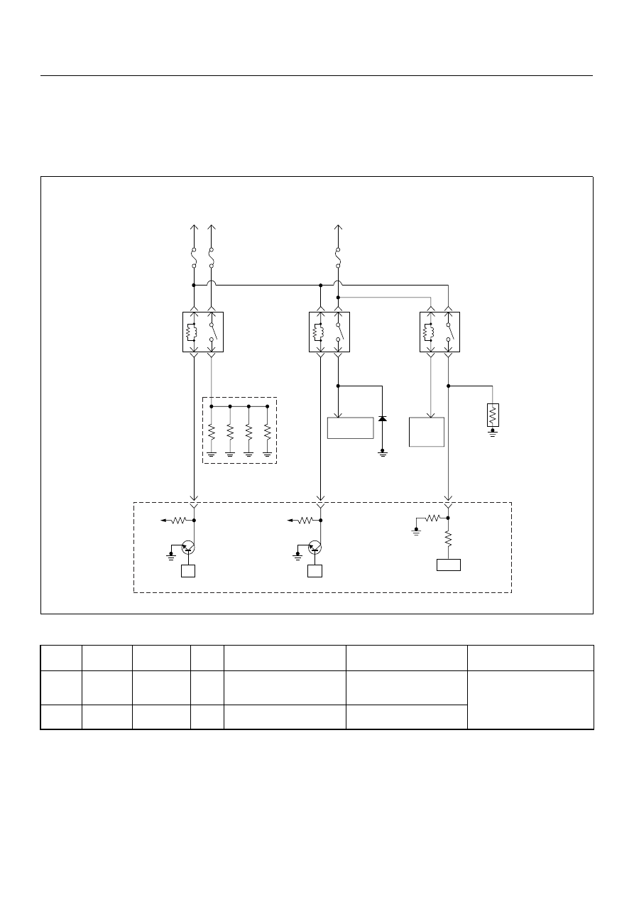
Circuit Description
The voltage on the coil of the A/C compressor is
supplied by the ECM main relay. The ECM switches A/C
compressor relay to operate A/C compressor depends
on the A/C request signal and certain setting conditions.
Diagnostic Aids
An intermittent may be caused by the following:
• Poor connections.
• Misrouted harness.
• Rubbed through wire insulation.
• Broken wire inside the insulation.
Flash
Code
Code
Symptom
Code
MIL
DTC Name
DTC Setting Condition
Fail-Safe (Back Up)
46
P0645
4
ON
A/C Compressor Relay Circuit
Voltage Low
A/C compressor relay circuit
open or short to ground cir-
cuit.
No fail-safe function.
8
ON
A/C Compressor Relay Circuit
Voltage High
A/C compressor relay circuit
short to voltage circuit.
Resister
A/C
Compressor
ECM
Main Relay
Battery
Voltage
Heater
Relay
Glow
50A
Glow
Relay
Glow
Plug
ECM
10A
0.5
BLU/
RED
0.5
BLK/
BLU
94
0.5
BRN/
RED
0.5
BLK
41
0.5
GRN
33
5.0
RED/
WHT
0.5
BLU/
RED
0.5
BRN/
YEL
0.5
GRY/
YEL
A/C
10A
0.5 BRN
A/C
Compressor
Relay
A/C
Thermo
Relay
0.5
BLU/
RED
5.0
BLK/
RED
Tripple
Pressure
SW
µP
Batt
µP
Batt
IC
Engine
Control
Module
(ECM)
6E–210
4JH1 ENGINE DRIVEABILITY AND EMISSIONS
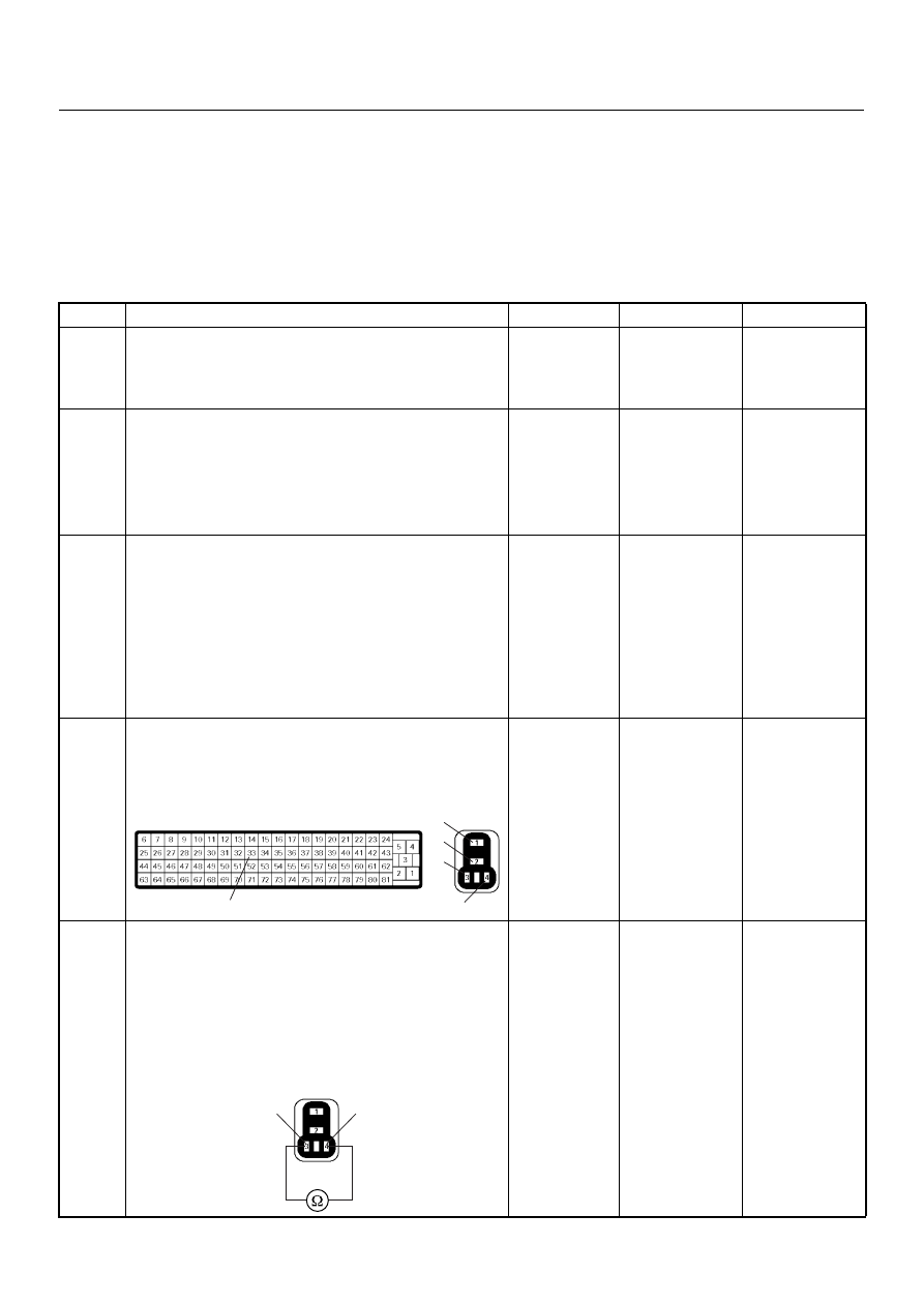
Check for the following conditions:
• Poor connection at ECM-Inspect harness connectors
for backed out terminals, improper mating, broken
locks, improperly formed or damaged terminals, and
poor terminal to wire connection.
• Damaged harness-Inspect the wiring harness for
damage. If the harness appears to be OK, observe
the DTC P0645 display on the Tech2 while moving
connectors and wiring harnesses.
Diagnostic Trouble Code (DTC) P0645 (Symptom Code 4) (Flash Code 46) A/C
Compressor Relay Circuit Voltage Low
Step
Action
Value(s)
Yes
No
1
Was the “On-Board Diagnostic (OBD) System Check”
performed?
—
Go to Step 2
Go to On Board
Diagnostic
(OBD) System
Check
2
1. Connect the Tech 2.
2. Review and record the failure information.
3. Select “F0: Read DTC Infor As Stored By ECU” in
“F0: Diagnostic Trouble Codes”.
Is the DTC P0645 (Symptom Code 4) stored as
“Present Failure”?
—
Go to Step 3
Refer to
Diagnostic Aids
and Go to Step
3
3
1. Using the Tech 2, ignition “On” and engine “Off”.
2. Select “F1: Clear DTC Information” in “F0:
Diagnostic Trouble Codes” with the Tech 2 and
clear the DTC information.
3. Operate the vehicle and monitor the “F0: Read
DTC Infor As Stored By ECU” in the “F0:
Diagnostic Trouble Codes”.
Was the DTC P0645 (Symptom Code 4) stored in this
ignition cycle?
—
Go to Step 4
Refer to
Diagnostic Aids
and Go to Step
4
4
Check for poor/faulty connection at the A/C
compressor relay or ECM connector. If a poor/faulty
connection is found, repair as necessary.
Was the problem found?
—
Verify repair
Go to Step 5
5
Using the DVM and check the A/C compressor relay.
1. Ignition “Off”, engine “Off”.
2. Remove the A/C compressor relay from the relay
box.
3. Check the relay coil.
Was the DVM indicated specified value?
Continuity
Go to Step 6
Replace A/C
compressor
relay and verify
repair
33
1
2
3
4
C-56
X-14
4
3
A/C Compressor Relay
X-14

4JH1 ENGINE DRIVEABILITY AND EMISSIONS
6E–211
6
Using the DVM and check the A/C compressor relay
power supply circuit.
1. Ignition “On”, engine “Off”.
2. Remove the A/C compressor relay from the relay
box.
3. Check the circuit for open or short to ground
circuit.
Was the DVM indicated specified value?
Battery
voltage
Go to Step 8
Go to Step 7
7
Repair the open or short to ground circuit between the
ECM main relay and A/C compressor relay.
Is the action complete?
—
Verify repair
—
Step
Action
Value(s)
Yes
No
3
V
X-14
Нет комментариевНе стесняйтесь поделиться с нами вашим ценным мнением.
Текст