Isuzu D-Max / Isuzu Rodeo (TFR/TFS). Manual — part 944
REAR AXLE 4B-13
Important Operations
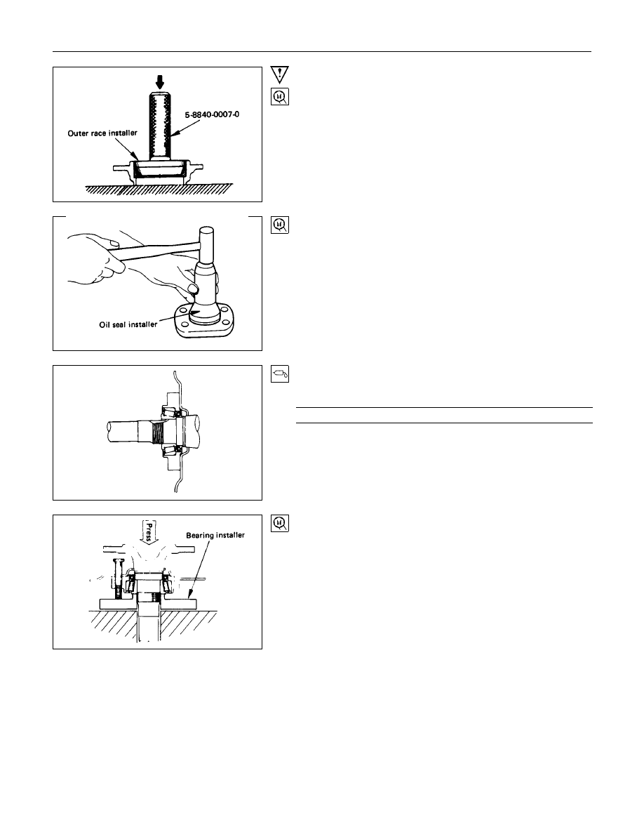
2. Bearing Outer Race
Installer : 5-8522-1268-0
(194 mm standard suspension)
(J-24259)
: 5-8840-2201-0
(194 mm heavy-duty suspension and 220 mm)
Grip
: 5-8840-0007-0 (J-8092)
3. Oil Seal ; Bearing Holder
Installer : 9-8522-1269-0
(194 mm standard suspension)
(J-24255)
: 5-8840-2202-0(194 mm H/D, 220 mm)
5. Bearing
Apply a generous amount of grease to the bearing inner race.
g(oz)
Approx. 30 (1)
6. Axle Shaft Assembly
7. Bearing Nut and Lock Washer
(1) Insert four through-bolts into the back plate.
(2) Install bearing holder to the back plate.
(3) Install the above parts onto the axle shaft.
(4) Install bearing over axle shaft and press it into bearing
holder.
Axle shaft bearing Installer : 9-8522-1271-0 (J-8609-01)
4B-14 REAR AXLE
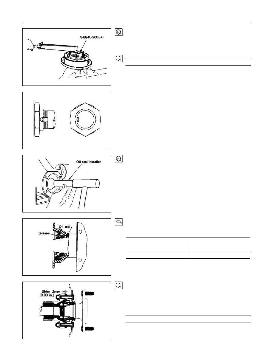
(5) Install the bearing nut into position by using a vise and the
special tool.
Installer : 5-8840-2003-0
(J-24246)
Torque
N
⋅
m (kgf
⋅
m/lb
⋅
ft)
260
±
5 (26.5
±
0.5/192
±
3.6)
(6) Position the chisel perpendicular to the center of the lock
nut groove.
Stake the lock nut.
8. Oil Seal ; Axle Case
Oil seal installer : 9-8522-1272-0 (J-24254)
(1) Apply measured amount of good quality grease to the inner
face of the rear axle case.
g(oz)
Type of grease
Wheel bearing grease or
Multipurpose type grease
Amount of grease required
80 (2.8)
9. Shim
Install the axle shaft assembly to the axle case with a 2 mm
(0.08 in) thick shim fit into position between the bearing holder
and axle case flange. Install and tighten the bolts evenly in
progression.
Torque
N
⋅
m (kg
⋅
m/lb
⋅
ft)
74
±
5 (7.5
±
0.5/54
±
3.6)
REAR AXLE 4B-15
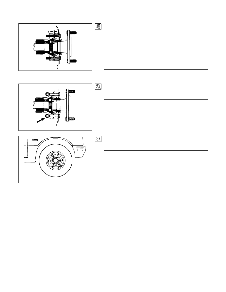
Install the axle shaft assembly on the opposite side and push it
in until it fits against the differential thrust block. Then,
measure the clearance (t) between the bearing holder and the
axle case flange and determine the thickness of the shim to be
installed by the following formula :
Measured clearance (t) + 0.3 mm (0.012 in) = thickness of
shim to be installed.
mm(in)
thickness of shims available
1.0, 0.5, 0.13, 0.076, 0.05
(0.036, 0.026, 0.005, 0.003, 0.002)
10.Bolt and Nut
Torque
N
⋅
m (kgf
⋅
m/lb
⋅
ft)
74
±
5 (7.5
±
0.5 / 54
±
3.6)
•
Connect the brake lines to wheel cylinder.
•
Connect the parking brake rear cable.
•
Brake air bleeding, refer to servicing to Section 5 brake.
Note :
To install the axle shaft assembly, follow the reassembly
procedure outline under the "BRAKE".
12.Wheel and Tire
Tighten the wheel nut in numerical order.
Torque
N
⋅
m (kgf
⋅
m/lb
⋅
ft)
117.7
±
9.8 (12
±
1/86.8
±
7.2)
4B-16 REAR AXLE
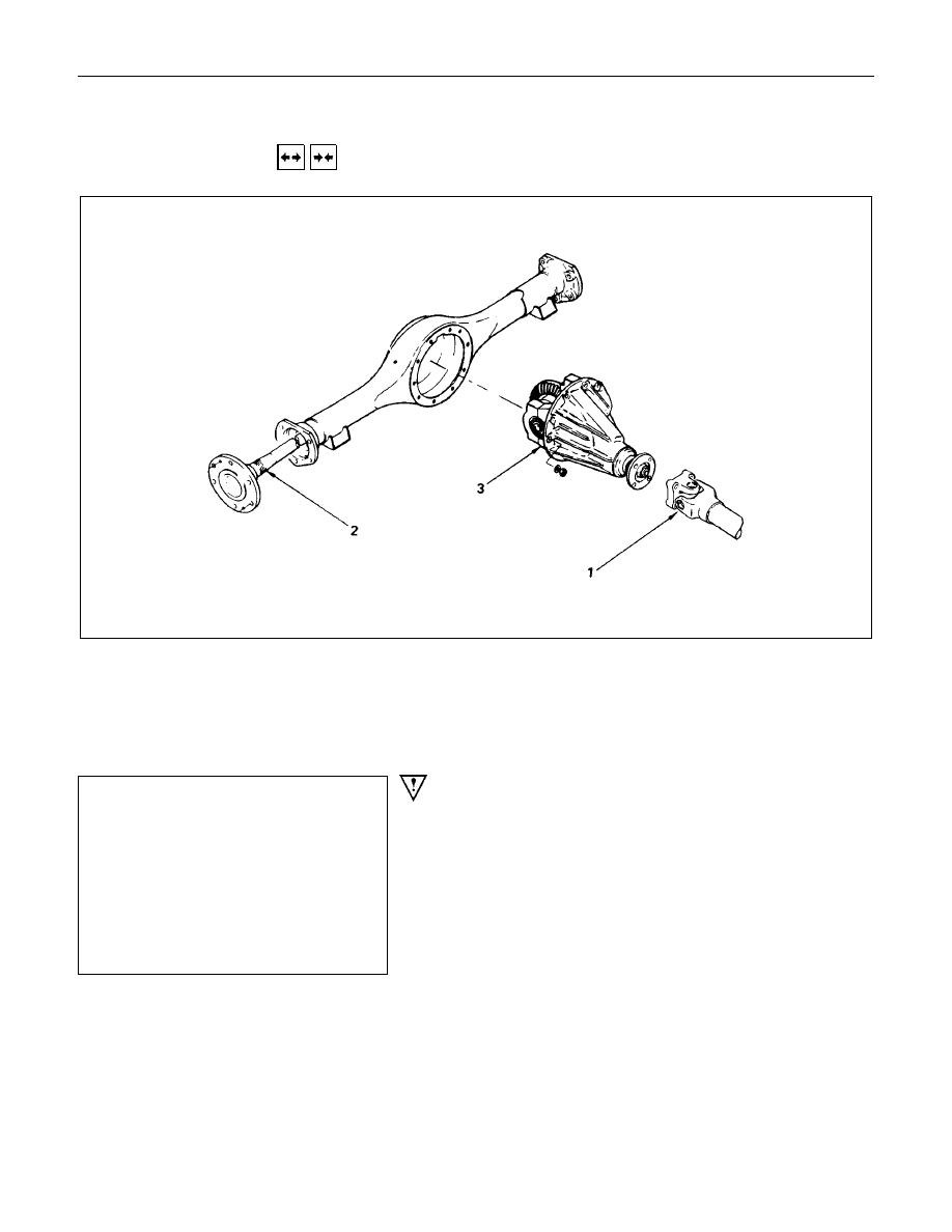
DIFFERENTIAL
REMOVAL AND INSTALLATION
Removal Steps
1. Propeller shaft
▲
2. Axle shaft
3. Differential assembly
Installation Steps
▲
3. Differential assembly
▲
2. Axle shaft
▲
1. Propeller shaft
To remove the axle shaft assembly,
follow the disassembly procedure outline
in this Section “Axle shaft”
Important Operation - Removal
2. Axle Shaft
Disengage the axle shafts from the carrier assembly and
partially withdraw the shafts from the axle tube.
It is not necessary to completely remove the axle shafts.
Move them only enough to allow the differential to be removed.
To remove the axle shaft assembly, follow the disassembly
procedure outline in this Section "Axle shaft".
Нет комментариевНе стесняйтесь поделиться с нами вашим ценным мнением.
Текст