Isuzu D-Max / Isuzu Rodeo (TFR/TFS). Manual — part 943
REAR AXLE 4B-9
Important Operations
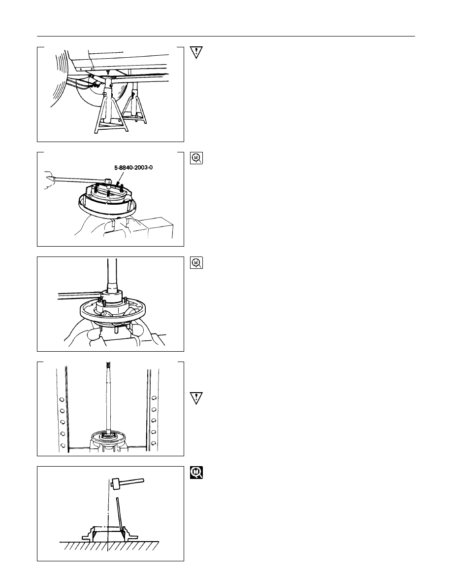
1. Wheel and Tire
Raise vehicle to the working level.
Support the axle assembly with the proper jack and chassis
stands.
6. Bearing Nut and Washer
<Standard Type Axle Shaft>
(1) Remove the stake from the lock nut.
(2) Mount axle shaft into vise, clamping vise jaws around the
lock nut.
Vise should not be tightened excessively on lock nut.
(3) Install special tool onto flange studs, lock into position with
two wheel nuts, and turn axle shaft loose from lock nut.
Remover and installer : 58840-2003-0 (J-24246)
<Heavy-Duty Type Axle Shaft>
(1) Remove the stake from the lock nut.
(2) Install special tool onto lock nut, and remove the lock nut.
Remover and installer : 5-8840-2329-0
7. Bearing Holder
Remove the bearing holder and bearing from the axle shaft by
means of a press.
NOTE :
Only a slight amount of pressure from the press is
required to separate the bearing from the shaft. Be sure to
support the backing plate solidly, and to hold onto the
axle shaft to prevent it from falling to the floor.
10.Bearing Outer Race
Drive off the bearing outer race using a brass drift.
4B-10 REAR AXLE
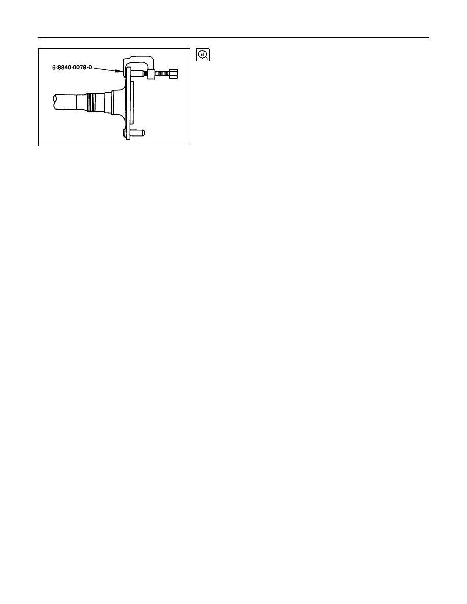
11.Wheel Pin
Remove the wheel pins from the axle shaft flange.
Remover : 5-8840-0079-0
(J-6627-A)

REAR AXLE 4B-11
INSPECTION AND REPAIR
Make all necessary adjustments, repairs, and part replacements if wear, damage, or other problems are discovered
during inspections.
Visual Check
Inspect the following parts for wear, damage or other abnormal
conditions.
Axle Shaft
When checking the axle shaft, pay special attention to the
splined portions and replace the shaft if distortion or step wear
is noticeable. Correct slight step wear with a pencil grinder.
Axle Shaft Run-Out
Check the shafts for bending with the use of a dial indicator in
contact with the shaft. Rotate the shaft slowly and observe the
dial indicator.
Limit
mm(in)
1.0 (0.039)
NOTE :
Never use heat to correct bending.
Axle Shaft Flange Run-Out
Check the axle shaft flange for run-out. Hold the probe of a
dial indicator in contact with the flange. Rotate the shaft slowly
and observe the dial.
Limit
mm(in)
0.08 (0.003)
4B-12 REAR AXLE
REASSEMBLY
1. Refer to Section 3E "WHEEL and TIRE" for road wheel reassembly procedure.
2. Refer to Section 5 "BRAKE" for rear brake installation procedure.
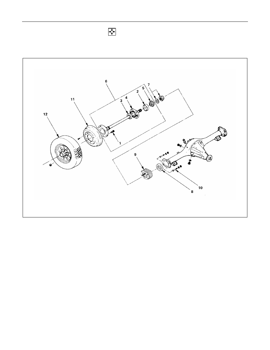
Reassembly Steps
1. Wheel pin
▲
2. Bearing outer race
▲
3. Oil seal
4. Bearing holder
▲
5. Bearing
▲
6. Axle shaft assembly
▲
7. Bearing nut and lock washer
▲
8. Oil seal
▲
9. Shim
▲
10. Bolt and nut
11. Brake drum
▲
12. Wheel and tire
Нет комментариевНе стесняйтесь поделиться с нами вашим ценным мнением.
Текст