Isuzu D-Max / Isuzu Rodeo (TFR/TFS). Manual — part 163
6E–256
4JH1 ENGINE DRIVEABILITY AND EMISSIONS
5
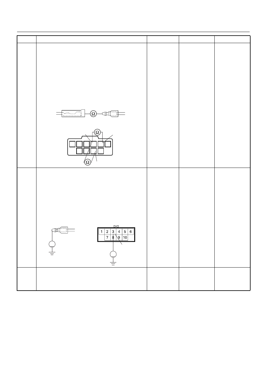
Using the DVM and check the neutral switch (inhibitor
switch).
1. Ignition “Off”, engine “Off”.
2. Remove the neutral switch connector (inhibitor
switch connector) at the transmission.
3. Check the neutral switch (P range N range
switch).
Was the DVM indicated specified value?
Neutral (P or
N): Continuity
Other than
neutral (P or
N): No
continuity Go
to
Step 6
Replace neutral
switch (inhibitor
switch) and
verify repair
6
Using the DVM and check the neutral switch (inhibitor
switch) power supply circuit.
1. Ignition “On”, engine “Off”.
2. Remove the neutral switch (inhibitor switch)
connector from the switch.
3. Check the circuit for open circuit.
Was the DVM indicated specified value?
Battery
voltage
Go to Step 8
Go to Step 7
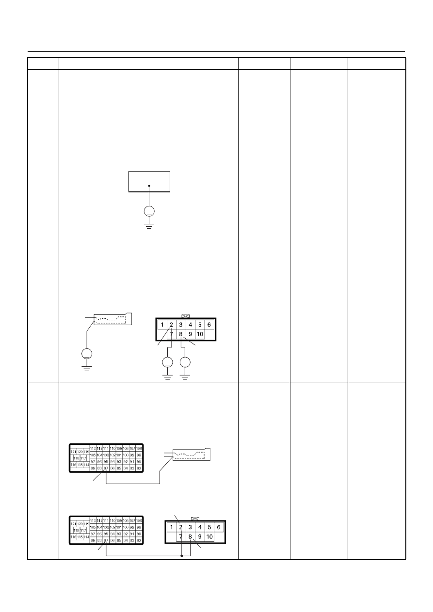
7
Repair the open circuit between the “ECM fuse (10A)”
and neutral switch (between the “Back Up fuse (15A)”
and inhibitor switch).
Is the action complete?
—
Verify repair
—
Step
Action
Value(s)
Yes
No
E-11
E-12
M/T
1
2
3
6
5
4
7
8
10
9
8
3
2
A/T
V
E-12
M/T
V
3
E-51
A/T
4JH1 ENGINE DRIVEABILITY AND EMISSIONS
6E–257
8
Using the DVM and check the neutral switch (inhibitor
switch) circuit.
Breaker box is available:
1. Ignition “Off”, engine “Off”.
2. Install the breaker box as type B. (ECM
connected) Ref. Page 6E-73
3. Ignition “On”, engine “Off”.
4. Check the circuit for open or short to voltage
circuit.
Was the DVM indicated specified value?
Breaker box is not available:
1. Ignition “On”, engine “Off”.
2. Back probe the DVM to the neutral switch (inhibitor
switch) and check the circuit for open or short to
voltage circuit.
Was the DVM indicated specified value?
Neutral (P or
N): Battery
voltage
Other than
neutral (P or
N): Less than
1V Go
to
Step 11
Fixed at battery
voltage: Go to
Step 9
Fixed at less
than 1V: Go to
Step 10
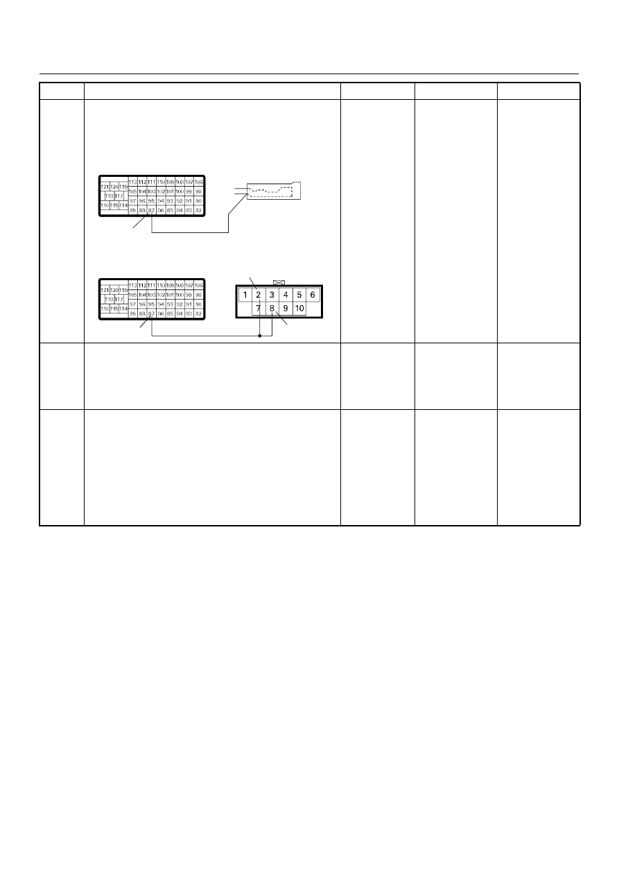
9
Repair the short to voltage circuit between the neutral
switch connector (inhibitor switch connector) and
ECM.
Is the action complete?
—
Verify repair
—
Step
Action
Value(s)
Yes
No
87
V
V
8
2
V
V
E-11
E-51
M/T
A/T
87
87
8
2
C-57
C-57
M/T
A/T
E-11
E-51
6E–258
4JH1 ENGINE DRIVEABILITY AND EMISSIONS
10
Repair the open circuit between the neutral switch
connector (inhibitor switch connector) and ECM.
Is the action complete?
—
Verify repair
—
11
Is the ECM programmed with the latest software
release?
If not, download the latest software to the ECM using
the “SPS (Service Programming System)”.
Was the problem solved?
—
Verify repair
Go to Step 12
12
Replace the ECM.
Is the action complete?
IMPORTANT: The replacement ECM must be
programmed. Refer to section of the Service
Programming System (SPS) in this manual.
Following ECM programming, the immobiliser system
(if equipped) must be linked to the ECM. Refer to
section 11 “Immobiliser System-ECM replacement” for
the ECM/Immobiliser linking procedure.
—
Verify repair
—
Step
Action
Value(s)
Yes
No
87
87
8
2
C-57
C-57
M/T
A/T
E-11
E-51

4JH1 ENGINE DRIVEABILITY AND EMISSIONS
6E–259
DIAGNOSTIC TROUBLE CODE (DTC) P1605 (SYMPTOM CODE C)
(FLASH CODE 55) SEED AND KEY FILE DESTROYED
DIAGNOSTIC TROUBLE CODE (DTC) P1605 (SYMPTOM CODE D)
(FLASH CODE 55) EEPROM DEFECT
DIAGNOSTIC TROUBLE CODE (DTC) P1605 (SYMPTOM CODE E)
(FLASH CODE 55) EEPROM DEFECT
Condition for setting the DTC and action taken when the DTC sets
Circuit Description & Diagnostic Aids
The ECM used in this vehicle utilizes an electrically
erasable & programmable read only memory
(EEPROM). The EEPROM contains program
information and the calibrations required for engine and
diagnostics operation.
If the ECM inside (IC, circuit, memory, etc,) failed, DTC
P1605 (Symptom Code C), P1605 (Symptom Code D)
or P1605 (Symptom Code E) will be stored.
Diagnostic Trouble Code (DTC) P1605 (Symptom Code C) (Flash Code 55)
Seed and Key File Destroyed
Diagnostic Trouble Code (DTC) P1605 (Symptom Code D) (Flash Code 55)
EEPROM Defect
Diagnostic Trouble Code (DTC) P1605 (Symptom Code E) (Flash Code 55)
EEPROM Defect
Flash
Code
Code
Symptom
Code
MIL
DTC Name
DTC Setting Condition
Fail-Safe (Back Up)
55
P1605
C
ON
Seed and Key File Destroyed
Seed or key file in EEPROM
is destroyed.
No fail-safe function.
D
ON
EEPROM Defect
Write and read from the
EEPROM are failed during ini-
tialization of the ECM.
ECM uses default values from
the EPROM.
E
ON
EEPROM Defect
EEPROM checksum does not
match with the read check
sum during initialization of the
ECM.
Step
Action
Value(s)
Yes
No
1
Was the “On-Board Diagnostic (OBD) System Check”
performed?
—
Go to Step 2
Go to On Board
Diagnostic
(OBD) System
Check
2
1. Connect the Tech 2.
2. Review and record the failure information.
3. Select “F0: Read DTC Infor As Stored By ECU” in
“F0: Diagnostic Trouble Codes”.
Is the DTC P1605 (Symptom Code C), P1605
(Symptom Code D) or P1605 (Symptom Code E)
stored as “Present Failure”?
—
Go to Step 3
Refer to
Diagnostic Aids
and Go to Step
3
Нет комментариевНе стесняйтесь поделиться с нами вашим ценным мнением.
Текст