Isuzu D-Max / Isuzu Rodeo (TFR/TFS). Manual — part 1007
10-28 CAB
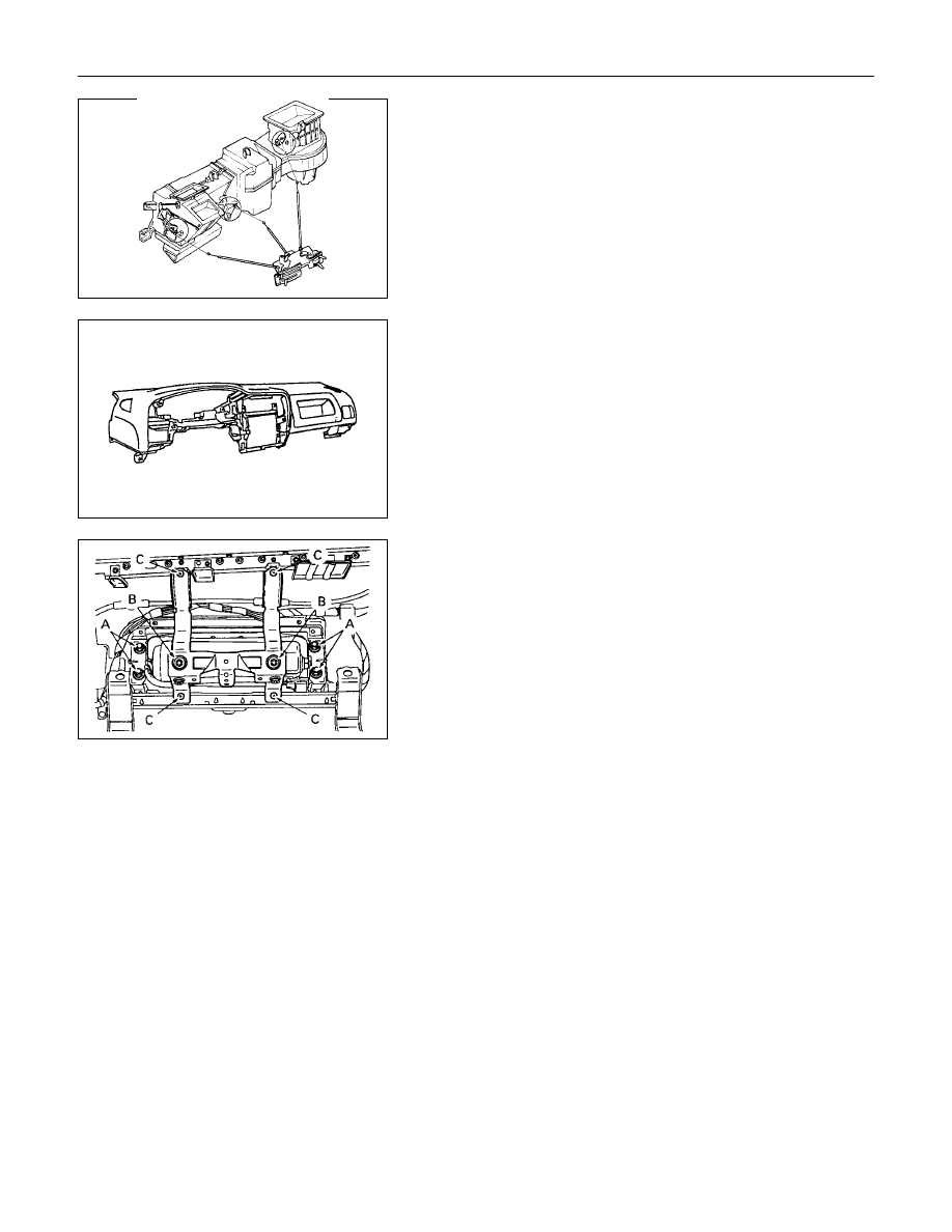
10.Control Lever Assembly
1) Disconnect the control cable from heater unit and blower
unit.
2) Remove the control lever assembly fixing screws.
11.Instrument Panel
1) Remove the instrument panel fixing nuts and bolts.
2) Disconnect the instrument harness connectors.
3) Remove the instrument panel.
Caution:
For precautions on installation or removal of SRS-air bag
system, refer to section 9 "Supplemental Restraint System
(SRS) - AIR BAG".
12a. Passenger air bag assembly
•
Remove 4 fixing bolts A and 2 nuts B.
Caution:
For precautions on installation or removal of SRS-air bag
system, refer to section 9 "Supplemental Restraint System
(SRS) - AIR BAG".
13.Passenger air bag reinforcement assembly (W/SRS)
•
Remove 4 fixing screws C.
CAB 10-29
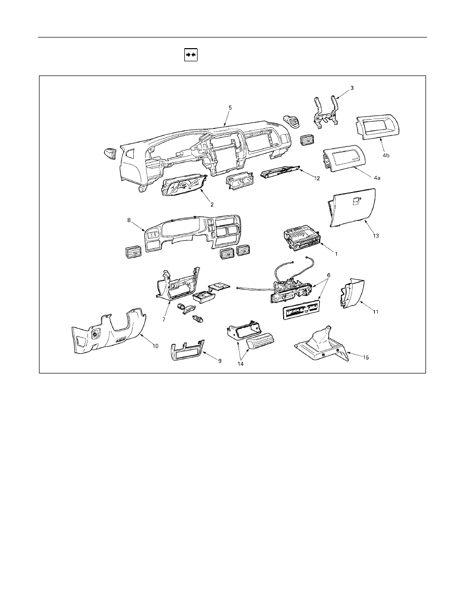
INSTALLATION
Installation Steps
1. Radio assembly
2. Meter assembly
3. Passenger air bag reinforcement
assembly
4a. Passenger air bag
4b. Utility box
5. Instrument panel assembly
V
6. Control lever assembly
7. Instrument panel lower center cover
assembly
8. Meter cluster assembly
9. Lower cluster assembly
10. Instrument panel driver lower cover
assembly
11. Instrument panel passenger lower cover
assembly
12. Glove box cover
13. Glove box
14. Control unit cover
15. Center console assembly
10-30 CAB
Important Operation - Installation
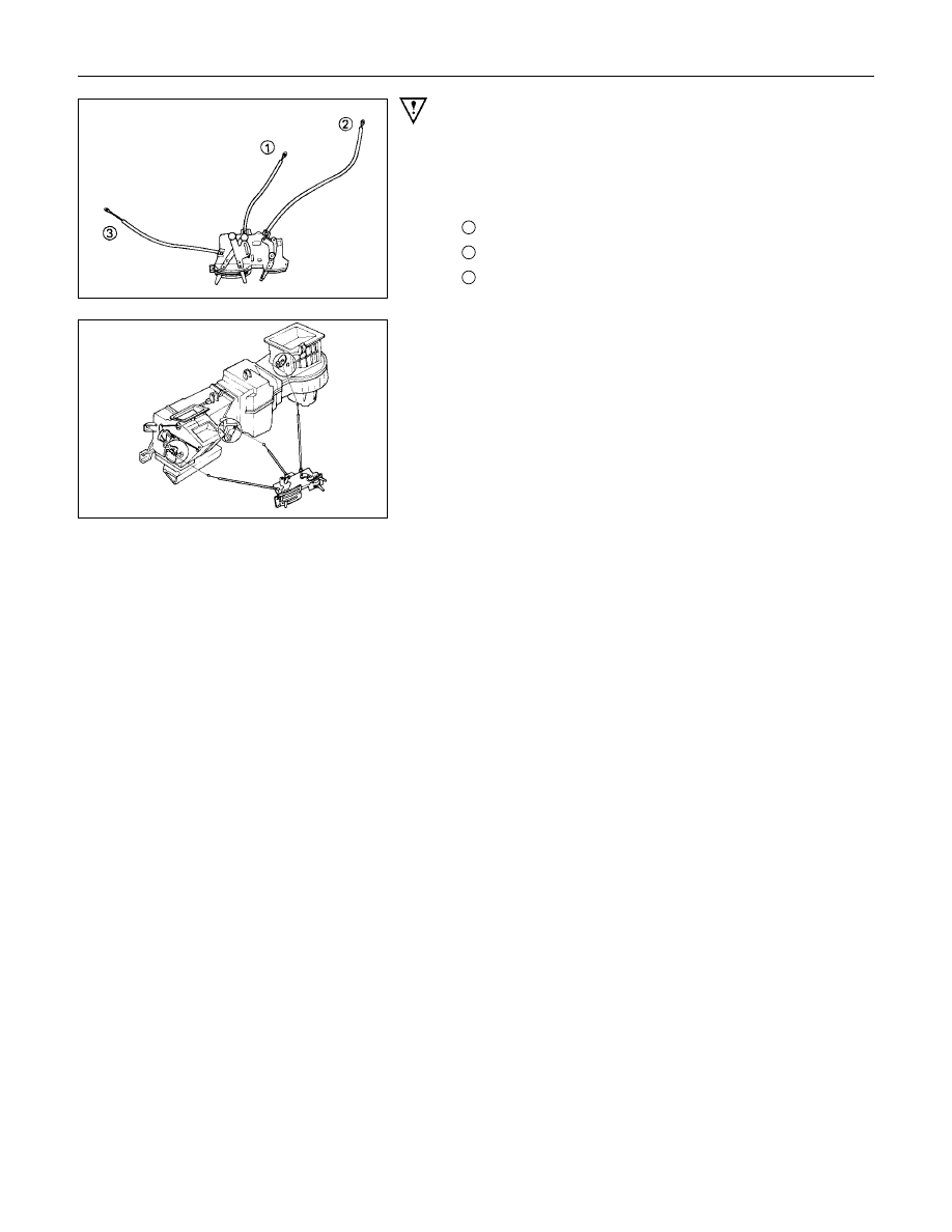
6. Control Lever Assembly
1) Set the temperature control lever and the airsource
select lever at the left-hand side end.
2) Set the air selector lever at the right-hand side end.
1
: Temperature control cable
2
: Air source select cable
3
: Air selector
3) Attach the cable, after the work 1) and 2) have been
completed.
CAB 10-31
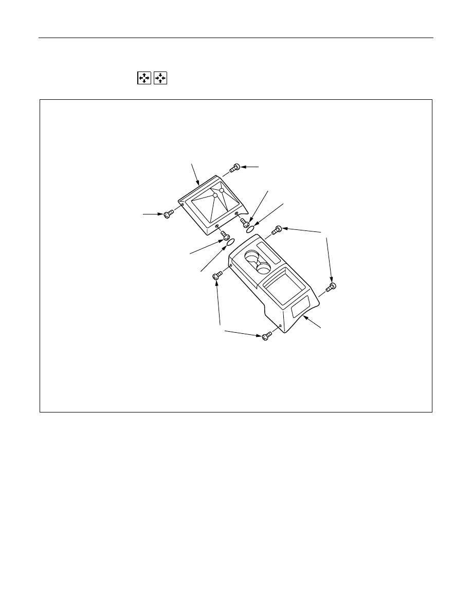
CONSOLE BOX
REMOVAL AND INSTALLATION
1
1
2
2
3
3
4
5
5
6
4
××××
4 S Model
Removal Steps
1. Hole cover
×
2
2. Screw
×
2
3. Screw
×
2
4. Center console
5. Screw
×
4
6. Rear console
Installation Steps
6. Rear console
5. Screw
×
4
4. Center console
3. Screw
×
2
2. Screw
×
2
1. Hole cover
×
2
Нет комментариевНе стесняйтесь поделиться с нами вашим ценным мнением.
Текст