Isuzu D-Max / Isuzu Rodeo (TFR/TFS). Manual — part 1006
10-24 CAB
Important Operations
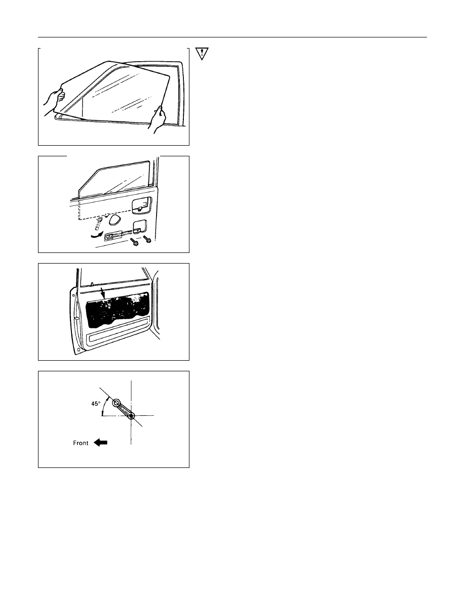
9.Window Glass
•
Insert the window glass into position by tilting it as
necessary, then set it against the channel of the window
regulator.
•
Attach the window glass to the window regulator with the
two screws.
10.Water Proof Sheet
•
Place the butyl type on the door panel so as not to cover
the drain hole.
25.Regulator Handle
•
Install the regulator handle as illustrated when closing
the window glass.
CAB 10-25
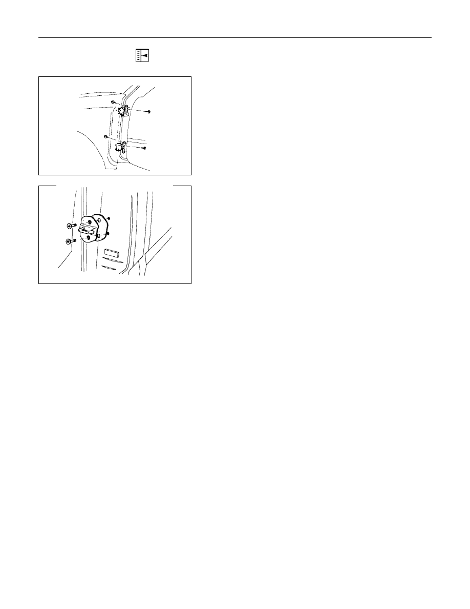
ADJUSTMENT (FRONT AND REAR)
Door Hinge
Door alignment can be obtained by moving door hinges.
Prior to adjustment, remove the fender and set the door
temporarily.
Loosen hinge to door bolts when adjusting steps between the
door and body.
Loosen hinge to body bolts to adjust the clearance between the
door and body.
Door Striker
Loosen the striker screws and adjust the position of the striker
by holding a piece of wood against the striker and tapping it
with a hammer.
To obtain correct adjustment, move the position of the striker
vertically so that the lower face of the dovetail becomes parallel
to the striker.
Adjust the number of sheets to control engagement of the
striker with the door latch. One or two sheets are generally
used to obtain correct adjustment.
10-26 CAB
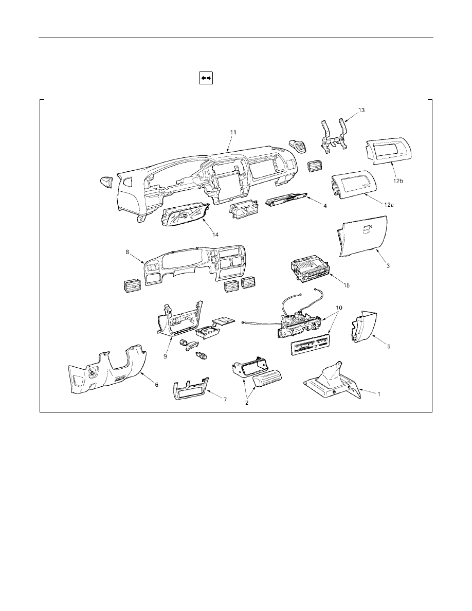
INSTRUMENT PANEL
REMOVAL
Disassembly Steps
V
1. Center console assembly
V
2. Control unit cover
V
3. Glove box
V
4. Glove box cover
V
5. Instrument panel passenger lower cover
assembly
V
6. Instrument panel driver lower cover
assembly
V
7. Lower cluster assembly
V
8. Meter cluster assembly
V
9. Instrument panel lower center cover
assembly
V
10. Control lever assembly
V
11. Instrument panel assembly
V
12a. Passenger air bag (if so equipped)
12b. Utility box
V
13. Passenger air bag reinforcement
assembly (W/SRS)
14. Meter assembly
15. Radio assembly
CAB 10-27
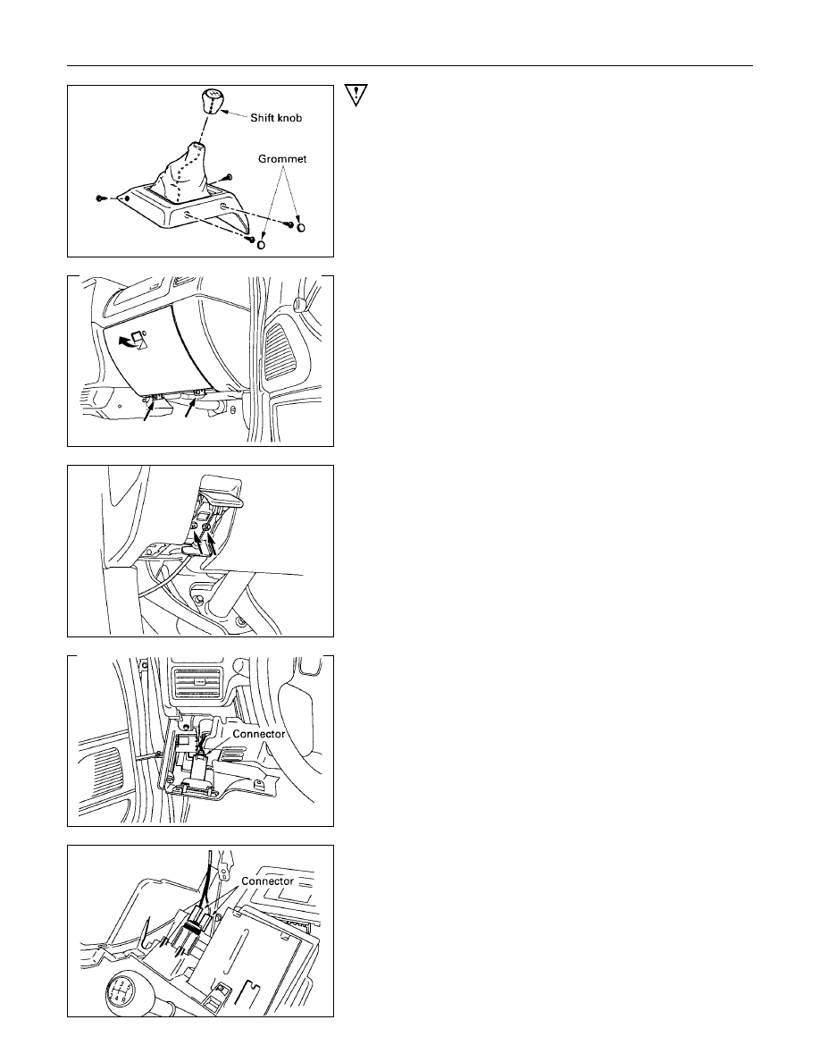
Important Operations
1. Center Console Assembly
•
Remove shift knob and 2 fixing screws (front side).
Open the grommet and remove 2 fixing screws (rear
side).
2. Control unit cover
3. Glove Box
•
Remove 2 fixing screws and pulling the handle.
4. Glove Box Cover
•
Remove 4 fixing screws and pull the cover toward you
and remove the clips at 2 positions.
5. Instrument Panel Passenger Lower Cover Assembly
•
Remove 3 fixing screws and 1 clip.
6. Instrument Panel Driver Lower Cover Assembly
•
Remove the engine hood opener 2 fixing screws and 6
fixing screws.
•
Disconnect the connector of the illumination.
7. Lower Cluster Assembly
•
Remove 3 fixing clips.
8. Meter Cluster Assembly
•
Remove 3 fixing screws, 7 clips and switch connectors.
9. Instrument Panel Lower Center Cover Assembly
•
Remove 7 fixing screws and disconnect the connector of
the cigarette lighter.
Нет комментариевНе стесняйтесь поделиться с нами вашим ценным мнением.
Текст